What Is a Damper and Why It Matters
Every time your air conditioner kicks on, a hidden blade inside your ductwork rotates to direct airflow exactly where it needs to go. That blade belongs to a damper — and if you've ever wondered what does a damper do or why certain rooms in your house feel warmer than others, this component is often the answer.
What Is a Damper in Simple Terms
So, what is a damper? The simplest way to define dampers is to think of them as valves — but for air, gas, or motion instead of water.
A damper is a mechanical device that regulates the flow of air, fluid, or motion by opening, closing, or partially obstructing a passageway. It controls how much resistance a moving substance or object encounters, allowing precise management of speed, volume, or direction.
That core dampers definition holds true whether you're looking at a metal blade inside an HVAC duct or a tiny rotary mechanism inside a soft-close toilet seat. The word itself traces back to the concept of "dampening" — reducing intensity or force. And that principle is exactly what every type of damper does, regardless of size or setting.
Where Dampers Are Used Every Day
You probably interact with dampers more often than you realize. Here are the major domains where they quietly do their job:
- HVAC ductwork — controlling which rooms receive heated or cooled air
- Fireplace flues — managing draft and preventing heat loss when the fireplace is not in use
- Industrial ventilation — regulating exhaust flow in factories and commercial kitchens
- Automotive systems — absorbing shock and vibration in suspensions
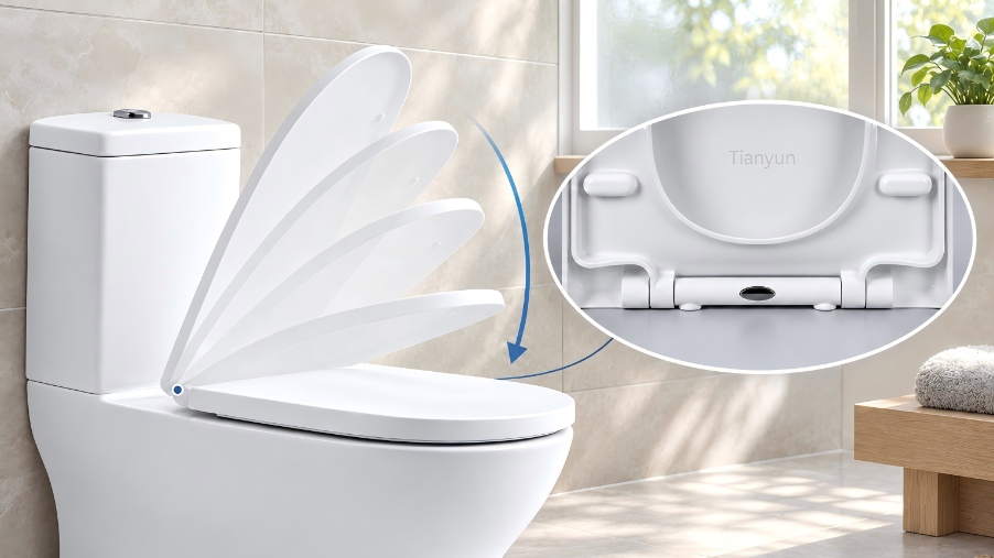
- Consumer products — providing smooth, controlled closing in soft-close lids, cabinet doors, and appliance covers
The specific mechanisms across these applications vary widely. A butterfly damper in a 24-inch commercial duct looks nothing like the compact rotary damper inside a kitchen trash can lid. Yet the underlying principle is universal: controlled resistance to movement. Every damper — whether it manages airflow through a building or slows the closing speed of a laptop screen — exists to prevent something from moving too fast, too freely, or in the wrong direction.
Understanding this principle matters for practical reasons. A malfunctioning damper in your HVAC system can spike energy bills by 12-18%, while a failed fire damper can put an entire building at risk. The mechanics behind that blade rotation, the actuator powering it, and the signals telling it when to move are worth understanding in detail.
The Step-by-Step Mechanics of How a Damper Physically Operates
That blade sitting inside your ductwork isn't just a piece of metal — it's a precision-engineered component with a specific range of motion, a drive mechanism, and a fail-safe behavior designed for your safety. Understanding how do dampers work at the component level reveals why some systems deliver perfect comfort while others leave rooms stuffy or freezing.
Blade Rotation and Airflow Restriction
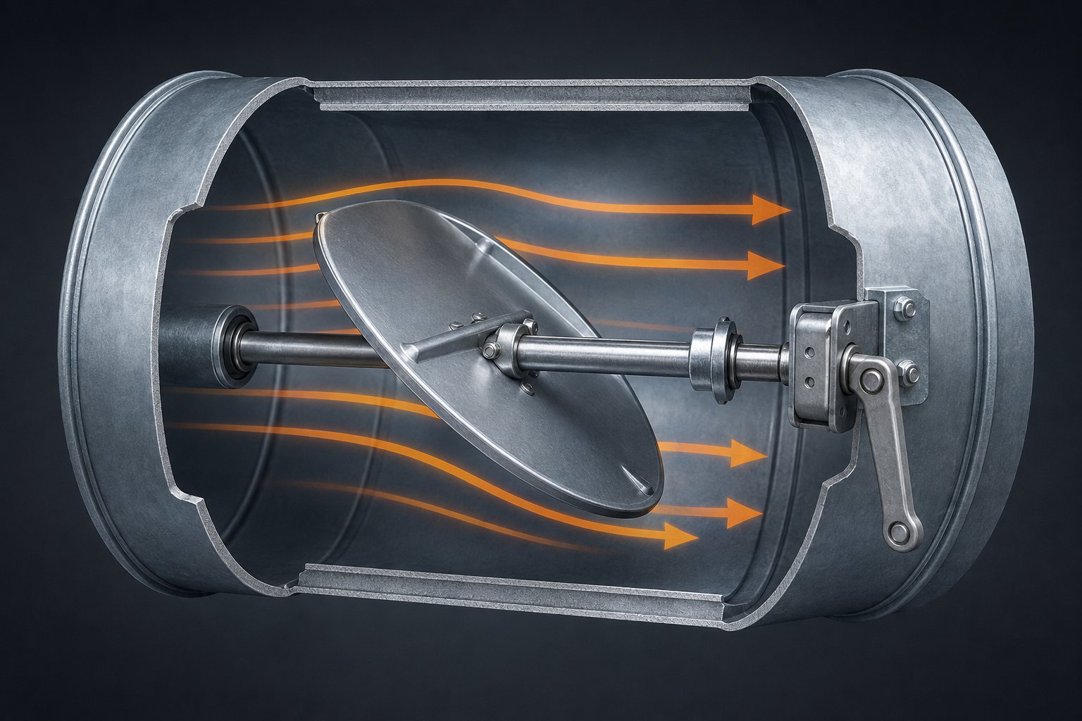
Imagine a flat disc mounted on a shaft running through the center of a round or rectangular duct. That disc is the damper blade, and its position relative to the airflow determines how much air passes through.
When the blade sits parallel to the airstream — aligned with the direction of airflow — air moves freely past it with minimal resistance. This is the fully open position. Rotate that blade 90 degrees so it sits perpendicular to the airstream, and it blocks the passageway almost entirely. This is the fully closed position. Every angle between those two extremes allows proportional control, letting you fine-tune exactly how much air reaches a specific zone.
The blade itself rotates on axles fixed to the damper frame. In a typical duct damper, one axle extends through the frame wall and connects to either a manual handle or an actuator on the outside. This extended axle is called the driving shaft. When that shaft turns, it moves the blade — and in multi-blade designs, a linkage system translates that rotation to every blade simultaneously. As MCDLG's engineering team explains, all blades rotate together with the driving blade at the same time, ensuring uniform airflow restriction across the entire damper face.
Blade profiles also matter. Single-thickness blades offer a tighter seal when closed, making them ideal when minimizing air leakage is the priority. Airfoil-shaped blades, on the other hand, reduce drag and pressure drop when fully open, allowing air to flow more efficiently. The choice between profiles depends on whether your air damper needs to prioritize sealing performance or open-flow efficiency.
How Control Signals Trigger Damper Movement
A blade that can rotate is useless without something telling it when and how far to move. That's where damper control signals come in — and the chain of events is more elegant than most people realize.
Here's the typical sequence: a thermostat or environmental sensor detects a condition — say, a room temperature that's drifted above the setpoint. That sensor sends an electrical signal (or in older commercial systems, a pneumatic signal using compressed air) to an actuator mounted on the damper. The actuator converts that signal into rotational force on the damper shaft, moving the blade to the commanded position.
The type of control signal determines how precisely the blade can be positioned:
- Two-position control — The simplest approach. The actuator receives an on/off signal and drives the blade to either fully open or fully closed. There's no middle ground. This is common for control dampers in basic zone systems where a room either needs air or doesn't.
- Floating-point control — The actuator receives open, close, or stop commands. It moves the blade incrementally in one direction until it receives a stop or reverse signal, allowing it to hold at intermediate positions without precise position feedback.
- Modulating control — The most precise option. The actuator receives a variable signal — typically 0-10V DC or 4-20mA — that corresponds to a specific blade angle. A 5V signal might command the blade to 50% open. This proportional approach allows dampers for air ducts to deliver exactly the right volume of conditioned air, adjusting continuously rather than simply slamming open or shut.
Modulating actuators are particularly valuable in commercial buildings where energy efficiency demands that airflow be matched precisely to real-time load conditions, not just toggled between extremes.
Normally Open vs Normally Closed Positions
Every damper has a default position — the state it returns to when power is removed or the control signal is lost. This isn't an arbitrary design choice. It's a safety decision that can protect lives, prevent equipment damage, or maintain building pressurization during an emergency.
A normally open damper defaults to the open position when power is lost. A normally closed damper defaults shut. In spring-return actuators, this behavior is driven by an internal spring that stores mechanical energy while the actuator is powered. When power fails, the spring releases and drives the blade to its predetermined safe position — a concept that industry sources describe as "power open, spring closed" or "spring open, power closed" depending on the configuration.
Here's when each default position is typically preferred:
- Normally closed is preferred when:
- Fire dampers must block flames and hot gases from spreading through ductwork during a fire event
- Zone control dampers should stop airflow to unoccupied areas during a power outage to prevent uncontrolled energy loss
- Outside air dampers need to seal against outdoor conditions when the system is not running
- Normally open is preferred when:
- Ventilation dampers must maintain fresh airflow for occupant safety even during a power failure
- Smoke control dampers need to allow smoke to exhaust to containment zones or exit points when the building loses power
- Pressure-relief dampers must prevent dangerous duct pressure buildup if the control system goes offline while the blower remains running
Getting this default position wrong carries real consequences. A fire damper that defaults open defeats its entire purpose. A ventilation damper that defaults closed could compromise indoor air quality during an emergency. The decision always comes back to one question: what is the safest state for this specific application when everything else fails?
The mechanics of blade rotation, signal processing, and fail-safe positioning work together as a single coordinated system. But the physical components carrying out these functions — the blades, actuators, and linkages — come in dramatically different configurations depending on the application. Those variations create an entire taxonomy of damper types, each engineered for a specific job.
Every Type of Damper and How Each One Works Differently
That taxonomy of blade configurations, actuator types, and default positions translates into a surprisingly wide family of damper designs — each purpose-built for a specific problem. When you look at the full range of types of dampers in HVAC and beyond, the differences go far deeper than shape or size. The mechanism, trigger, and control method change dramatically from one type to the next.
HVAC Damper Types at a Glance
The table below maps every major damper category against its core mechanics, primary application, and control method. You'll notice that the first entry extends beyond ductwork entirely — a reminder that damping principles apply well outside the HVAC world.
| Type | How It Works Mechanically | Primary Use Case | Control Method |
|---|---|---|---|
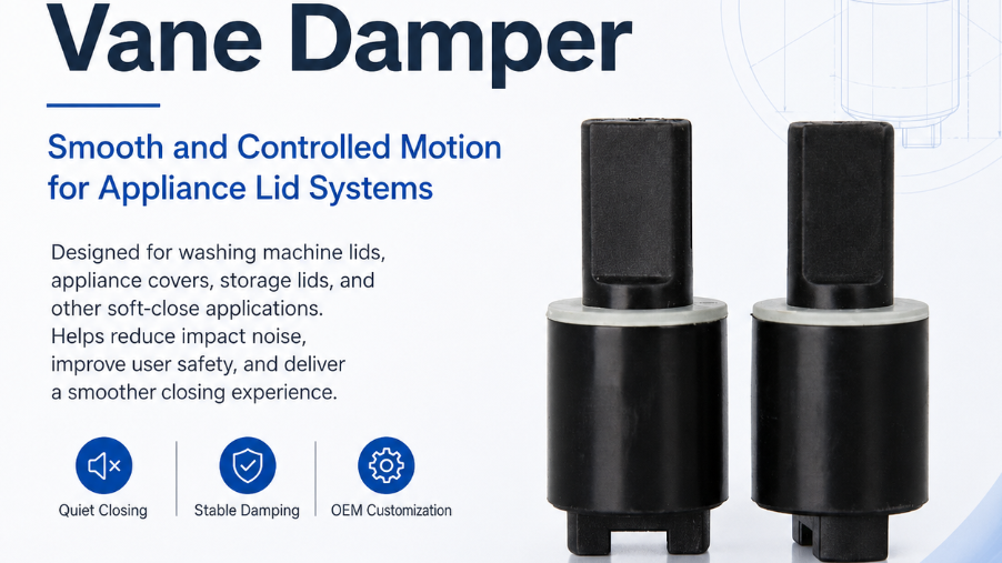
| Vane Rotary Damper | Uses internal vanes rotating through viscous fluid to create controlled resistance to rotational motion | OEM motion control in consumer products — soft-close toilet seats, appliance lids, compact mechanical assemblies | Passive (self-contained, no external signal needed) |
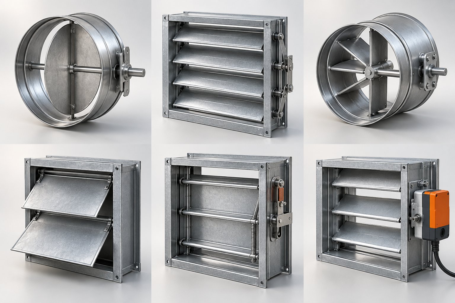
| Butterfly Damper | Single circular disc rotates on a central shaft inside a round duct | Round duct airflow regulation, volume damper HVAC applications | Manual handle or motorized actuator |
| Blade/Louver Damper | Multiple parallel blades rotate simultaneously via a linkage system for tighter sealing | Rectangular duct airflow control, commercial air handling units | Motorized actuator (modulating or two-position) |
| Backdraft Damper | Lightweight blades swing open under positive airflow pressure; gravity closes them when airflow stops | Exhaust systems — preventing reverse airflow through kitchen or bathroom vents | Automatic (gravity-operated, no signal required) |
| Zone Damper | Motorized blade opens or closes based on thermostat calls from individual zones | Residential and commercial zoning systems directing conditioned air to occupied areas | Electric actuator controlled by zone control panel |
| Balancing Damper | Manually adjusted blade set to a fixed position during system commissioning to equalize airflow | Fine-tuning air distribution across multiple duct branches | Manual (set once, rarely readjusted) |
| Bypass Damper | Opens to redirect excess supply air back to the return plenum when zone dampers restrict flow | Pressure relief in zoned HVAC systems | Automatic (pressure-activated) or motorized |
| Fresh Air Damper | Opens to admit outdoor air into the HVAC system for ventilation; closes to seal against outdoor conditions | Outdoor air intake for ventilation compliance and indoor air quality | Motorized actuator or economizer control |
| Fire Damper | Spring-loaded blade held open by a fusible link; link melts at a set temperature and blade snaps shut | Fire-rated wall and floor penetrations — blocking flame and hot gas spread through ductwork | Automatic (thermal trigger via fusible link) |
| Smoke Damper | Actuator-driven blade closes in response to signals from smoke detectors or fire alarm panel | Smoke containment in commercial buildings | Electric actuator triggered by detection system |
| Combination Fire/Smoke Damper | Incorporates both a fusible link for thermal response and an electric actuator for smoke detection signals | Duct penetrations requiring dual-trigger protection | Thermal (fusible link) + electric actuator |
For product designers exploring the motion-control end of this spectrum, Tianyun's Vane Rotary Dampers offer a practical example of how compact vane-based mechanisms deliver smooth, controlled closing performance in everyday consumer products — from toilet seats to appliance covers.
How Butterfly and Louver Dampers Differ Mechanically
These two types handle the same basic job — regulating airflow volume inside ductwork — but their internal designs serve different priorities.
A butterfly damper uses a single circular disc mounted on a central shaft. When you rotate that shaft, the disc pivots to restrict or allow airflow. It's a clean, simple mechanism that works especially well in round ducts. Because there's only one moving part, butterfly dampers create even pressure across the duct cross-section and are easier to access for repairs or upgrades. If you need a straightforward volume damper in a residential branch line, this is often the go-to choice.
Louver dampers (also called multi-blade dampers) take a different approach. Instead of a single disc, they use several parallel blades connected by a linkage mechanism so all blades rotate together. This design provides two distinct advantages: tighter sealing when fully closed and finer control over airflow at intermediate positions. The parallel blade arrangement also fits rectangular duct profiles more naturally, which is why louver dampers dominate in commercial air handling units and large rectangular ductwork. As EB Air Control notes, damper blades are movable and act as regulators — a distinction that separates them from fixed-blade louvers used purely for weather protection.
Opposed-blade louver dampers add another layer of refinement. Their blades rotate in alternating directions, which produces a more uniform airflow pattern at partial openings compared to parallel-blade versions. If your application demands precise modulating control with minimal turbulence — think balancing dampers in a critical zone system — opposed-blade configurations are the better mechanical fit.
Specialty Dampers for Pressure Management
Airflow volume isn't the only thing dampers control. Several specialty types exist specifically to manage pressure imbalances that could damage ductwork, waste energy, or make doors nearly impossible to open.
Bypass dampers solve a common problem in zoned HVAC systems. When a zone damper closes off one branch, the blower is still pushing the same total volume of air — and that excess air needs somewhere to go. A bypass damper opens automatically (or via a motorized actuator) to redirect that surplus air from the supply plenum back to the return plenum, relieving pressure buildup and protecting the blower motor from working against a restricted system.
Barometric dampers operate on a beautifully simple principle. Lightweight metal blades are counterweighted to swing open only when indoor pressure rises above a specific threshold — typically around 0.1 inches of water column. When pressure normalizes, gravity swings the blades shut. These are commonly installed on the return-air side of economizer systems to vent excess air when a fresh air damper introduces outdoor air for ventilation. No wiring, no actuators, no control signals — just physics doing the work.
Pressure-relief dampers serve a similar function but are spring-loaded rather than gravity-dependent. This makes them suitable for vertical installations or environments where orientation prevents gravity-operated blades from functioning reliably. They crack open at a predetermined pressure setpoint and reclose when pressure drops, providing a fail-safe release valve for ductwork that might otherwise buckle or leak at seams under excessive positive pressure.
Each of these specialty types addresses a scenario where standard airflow dampers fall short. Yet regardless of type — whether it's a zone damper directing conditioned air to your bedroom or a barometric damper quietly exhausting overpressure from a rooftop unit — the question of how that blade gets moving comes down to one of three approaches: manual force, motorized actuation, or automatic response.
Manual vs Motorized vs Automatic Dampers Compared
Those three approaches — manual force, motorized actuation, and automatic response — represent fundamentally different philosophies of control. A manual damper relies entirely on human hands. A motorized damper takes commands from a thermostat or building automation system. And an automatic damper skips external signals altogether, reacting directly to physical forces like airflow pressure or temperature change. Choosing the right one depends on how often adjustments need to happen, how fast the response needs to be, and whether anyone will actually be around to make the adjustment.
How Manual Dampers Work
Picture a small metal handle sticking out from the side of a duct. That handle connects directly to the damper blade inside via a shaft running through the duct wall. You physically rotate the handle, the shaft turns, and the blade moves to whatever angle you set. That's it — no wiring, no motors, no signals.
The marking convention is simple and worth knowing: when the handle sits parallel to the duct, the damper is open and air flows freely. Rotate the handle perpendicular to the duct, and the blade blocks airflow. Some manual dampers include a locking mechanism — often called a hand quadrant — that holds the blade at the selected angle so vibration or air pressure doesn't push it out of position. As Greenheck's engineering team explains, manual balancing dampers use this hand quadrant to set the blade position and lock it in place, making them the lowest-cost option for accessible locations.
You'll find manual dampers HVAC technicians set during initial system commissioning — the process of balancing airflow across all duct branches so every room receives its designed air volume. Once set, these hvac manual dampers rarely need readjustment unless the duct layout changes or occupancy requirements shift. They're reliable precisely because there's nothing electronic to fail. The tradeoff? They can't respond to changing conditions on their own. If a conference room fills with 30 people and suddenly needs more cooling, that manual blade stays exactly where the technician left it.
How Motorized Dampers Work
Replace the manual handle with a small electric motor, and you get a motorized damper — a blade that moves on command from a thermostat, zone control panel, or building automation system without anyone touching the ductwork.
The motor doesn't spin the blade directly. Instead, it drives through a gear reduction mechanism that converts high-speed, low-torque motor rotation into slow, high-torque shaft movement. Imagine a tiny motor spinning at several hundred RPM being geared down to rotate the damper blade at roughly 1-2 degrees per second. That deliberate slowness isn't a design flaw — it's intentional. A blade that snaps open or shut would create pressure spikes in the ductwork and generate disruptive noise. The gear train ensures smooth, gradual movement that the system absorbs without stress.
Motorized dampers typically run on one of two voltage levels:
- 24V actuators — the most common in residential and light commercial systems. They use low-voltage wiring from a transformer, making them safer for homeowner-accessible installations and compatible with standard HVAC thermostat circuits.
- Line-voltage actuators (120V or 230V) — found in larger commercial and industrial systems where higher torque is needed to move bigger blades or overcome greater air pressure. These require dedicated electrical circuits and professional installation.
Electric dampers receive their commands through several signal types. Two-position actuators simply receive an open or close signal and drive the blade to one extreme or the other. Modulating actuators accept variable signals — commonly 0-10V DC or 4-20mA — and position the blade proportionally. A 7V signal on a 0-10V actuator, for example, drives the blade to approximately 70% open. This proportional control is what makes a motorized damper valuable in zoning systems where each room may need a different volume of conditioned air at any given moment.
How Automatic Dampers Respond Without External Signals
Some dampers need no electricity, no wiring, and no control commands at all. Automatic dampers respond directly to the physical conditions around them, using forces like gravity, air pressure, or heat to drive their own blade movement.
Gravity-operated backdraft dampers are the most common example. Their lightweight blades hang vertically in a closed position when no air is moving. When a fan or blower pushes air through the duct, that positive pressure swings the blades open. The instant the fan shuts off and airflow stops, gravity pulls the blades back to closed — preventing outdoor air, insects, or exhaust fumes from backflowing into the building. No thermostat involved. No actuator humming. Just physics.
Thermal automatic dampers take a different approach. These use bimetallic elements — strips made of two metals with different expansion rates bonded together — that physically bend when temperature changes. As surrounding air heats up, the bimetallic strip curves and mechanically drives the blade to a new position. Fusible link dampers work on a similar temperature-response principle: a heat-sensitive metal connector holds the blade in its normal position, then melts at a predetermined temperature (commonly 165°F or 212°F) to release a spring-loaded blade. Fire dampers rely on this exact mechanism — no power supply, no control wiring, just a metallurgical trigger that activates when it matters most.
The table below puts all three approaches side by side so you can see exactly where each one fits best:
| Feature | Manual Damper | Motorized Damper | Automatic Damper |
|---|---|---|---|
| Mechanism | Handle-and-shaft connected directly to blade; human force rotates blade | Electric motor with gear reduction drives blade via control signal | Gravity, air pressure, or thermal expansion moves blade without external input |
| Speed of Response | Depends on how quickly a person can access and adjust the handle | 15-90 seconds for full travel (depending on actuator model) | Near-instantaneous for backdraft; seconds to minutes for thermal types |
| Installation Complexity | Low — no wiring, mount in duct and attach handle | Moderate — requires wiring to thermostat, zone panel, or BAS | Low — no wiring; position correctly in duct and verify orientation |
| Typical Cost Range | Lowest (damper body plus hand quadrant only) | Moderate to high (damper body plus actuator, wiring, and controls) | Low to moderate (self-contained mechanism, no accessories needed) |
| Best Use Case | Initial airflow balancing during HVAC commissioning; set-and-forget applications | Active zoning systems, smart thermostat integration, variable air volume control | Backdraft prevention in exhaust systems; fire and smoke safety shutoffs |
Each category handles the "how" of blade movement differently, but they all depend on one shared component to translate force into rotation: the actuator. Even manual dampers use a basic version of this concept — the handle and shaft are, in essence, a human-powered actuator. The differences between electric, pneumatic, and spring-return actuators determine not just how a damper moves, but how reliably it fails safe when the unexpected happens.
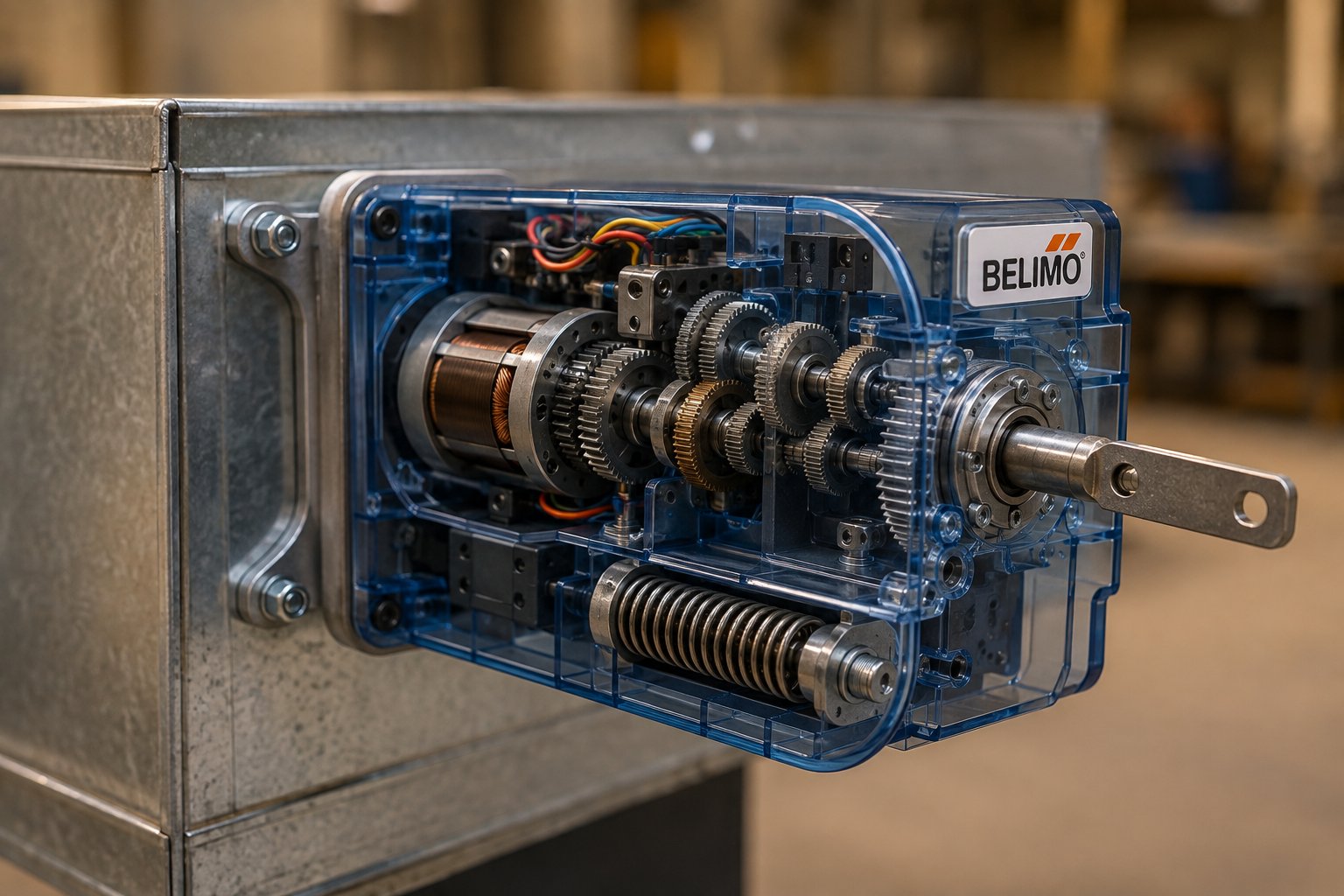
How Actuators Power Damper Movement
A damper blade can be perfectly engineered, perfectly sized, and perfectly sealed — but it's useless if nothing drives it to the right position at the right time. The actuator is that driving force, and it's arguably the single most important component in answering how does a damper work in practice. Think of the actuator as the muscle attached to the skeleton of the damper assembly. It receives a command, converts energy into rotational force, and physically moves the blade. The type of actuator installed determines how fast, how precisely, and how safely the damper operates — and what happens when things go wrong.
Electric Actuators and Gear Trains
The most widely used damper motor HVAC systems rely on is the electric actuator. Inside its compact housing sits a small electric motor — typically drawing between 3 and 10 watts — connected to a multi-stage gear train. That gear train is doing critical work. The motor itself spins relatively fast but produces very little torque on its own. The gears step down that speed and multiply the torque, converting rapid rotation into the slow, powerful shaft movement needed to push a damper blade against air pressure.
Imagine a motor spinning at 1,500 RPM being geared down through three or four reduction stages until the output shaft rotates at roughly 1-2 degrees per second. That deliberate pace isn't a limitation — it's engineered. A blade that snaps from open to closed would hammer the ductwork with pressure spikes and generate noise that occupants would hear through every register in the building.
What separates basic electric dampers HVAC installations from high-performance ones is the control signal the actuator accepts. There are three distinct approaches:
- On/off (two-position) control — The simplest scheme. The actuator receives a single signal and drives the blade to fully open or fully closed. No middle positions. This works for straightforward applications where a zone either needs air or doesn't.
- Floating-point (three-point) control — A step up in sophistication. The actuator accepts three states: open, close, and stop. One input drives the blade clockwise, the other drives it counterclockwise, and when neither input is energized, the actuator holds its current position. This allows intermediate blade angles without requiring precise position feedback from the actuator itself — the controller decides when to send the stop signal based on sensor readings.
- Modulating (proportional) control — The most precise option. The actuator varies its position proportionally with an analog signal from the controller. Common signal ranges include 0-10V, 2-10V, or 4-20mA. A 5V signal on a 0-10V actuator commands the blade to approximately 50% open. This level of hvac damper control is essential in variable air volume (VAV) systems and energy-conscious commercial buildings where airflow must track real-time demand continuously.
Proportional control is where motorized damper HVAC installations deliver their greatest value. Instead of cycling between extremes, the blade adjusts incrementally — matching conditioned airflow to the actual thermal load in each zone. The result is tighter temperature control, quieter operation, and measurable energy savings compared to simple on/off approaches.
Pneumatic Actuators in Commercial Systems
Walk into a large commercial building built before the 2000s, and there's a strong chance the hvac dampers motorized by pneumatic actuators are still doing their job reliably. Pneumatic actuation uses compressed air — typically supplied at 15-20 PSI from a central compressor — as the motive force instead of an electric motor.
The mechanism is straightforward. Compressed air enters the actuator housing and pushes against a flexible diaphragm or a piston. That mechanical displacement is transferred through a linkage to the damper shaft, rotating the blade. Increase the air pressure, and the blade moves further open. Decrease it, and a return spring or opposing air chamber drives the blade back. The amount of air can be moderated to deliver precise control over the actuator's movement, making pneumatic systems fully capable of proportional positioning — not just on/off switching.
Why does pneumatic actuation persist in an era of digital everything? Several practical reasons:
- Speed — Pneumatic actuators can move a damper blade from fully open to fully closed in under two seconds, far faster than most electric gear-driven actuators. In smoke control and exhaust applications where response time is critical, that speed advantage matters.
- Reliability in harsh environments — No circuit boards, no capacitors, no electronic components vulnerable to moisture, heat, or electrical interference. Compressed air works in environments that would destroy sensitive electronics.
- Established infrastructure — Many large commercial facilities already have compressed air distribution networks for other building systems. Adding pneumatic damper actuators to an existing air supply is often simpler and cheaper than running new electrical circuits.
The tradeoff is infrastructure overhead. A pneumatic system requires a compressor, air dryers, pressure regulators, and tubing — all of which need their own maintenance. For new construction, electric actuators have largely won the cost-benefit analysis. But in retrofit situations where pneumatic lines are already in place, replacing them with electric alternatives often creates more problems than it solves.
Spring-Return Actuators as a Safety Mechanism
Every actuator type described so far shares one vulnerability: they all need a power source to move the blade. So what happens when the power goes out? A standard electric actuator simply freezes in whatever position it occupied at the moment of failure. If that position happens to be wrong — an outside air damper stuck wide open during a winter power outage, for instance — the consequences can range from frozen coils to burst pipes.
Spring-return actuators solve this problem with elegant mechanical simplicity. While the actuator is powered and driving the blade to its commanded position, it simultaneously tensions a coiled spring inside the housing. Energy flows in two directions: into rotating the blade and into storing potential energy in the spring. The motor must generate essentially double the torque — enough to overcome both the damper load and the spring resistance — which is why spring-return actuators are larger and more expensive than their non-spring counterparts.
The payoff comes during a power failure. The instant electricity is lost, the spring releases its stored energy and drives the damper blade to a predetermined safe position — fully closed for fire dampers, fully open for ventilation dampers — without requiring backup power, batteries, or any human intervention. The entire fail-safe cycle completes in seconds.
A newer alternative — the electronic fail-safe actuator — uses capacitors instead of springs to store energy. Capacitors hold an electrical charge while power is supplied and release it during an outage, driving the motor back to the safe position electronically. This eliminates the extra torque penalty of fighting a spring on every movement cycle, resulting in a more energy-efficient and compact design while still achieving the same fail-safe behavior.
Here's a quick reference for matching the right actuator type to the right job:
- Electric actuator — Key advantage: precise proportional positioning with simple wiring. Best for zone dampers, VAV boxes, and any application requiring modulating control in residential or commercial systems.
- Pneumatic actuator — Key advantage: fast response and durability in harsh environments. Best for large commercial and industrial dampers where compressed air infrastructure already exists and rapid actuation speed is required.
- Spring-return actuator — Key advantage: guaranteed fail-safe operation without backup power. Best for fire dampers, smoke dampers, outside air dampers, and any application where the blade must reach a safe position during a power failure.
These actuators don't operate in isolation. Each one sits within a larger control ecosystem — receiving commands from thermostats, zone panels, and increasingly, smart building platforms that coordinate dozens of dampers simultaneously. The way those signals flow from sensor to actuator to blade, and how modern zoning systems orchestrate the entire chain, determines whether a building delivers consistent comfort or frustrating hot and cold spots.
How Dampers Work with Zoning Systems and Smart Thermostats
A single damper responding to a single signal is straightforward enough. But most real-world HVAC installations don't rely on just one damper — they coordinate several, opening and closing blades across multiple duct branches simultaneously so that conditioned air reaches only the rooms that actually need it. That coordination requires a system, and the signal chain connecting your thermostat to the damper blade involves more steps than most homeowners realize.
The Signal Chain from Thermostat to Damper
What are dampers in HVAC if not the physical gatekeepers of a larger intelligence network? Each zone damper sits inside a branch duct, waiting for instructions. But those instructions don't come directly from the thermostat on your wall. They pass through a central coordinator first — the zone control panel.
Here's how the full sequence plays out. Imagine your upstairs bedroom thermostat registers 78°F while the setpoint is 73°F. That thermostat sends a call for cooling to the zone control panel — a small circuit board typically mounted near your air handler or furnace. The panel receives that call and makes two simultaneous decisions: it sends an "open" command to the actuator on the upstairs zone damper, and it signals the HVAC equipment to start running. Meanwhile, if the downstairs zone is already at its setpoint, the panel keeps the downstairs hvac zone dampers closed, directing all available conditioned air upstairs where it's needed.
The zone control panel acts as the brain of this hvac damper system, and its role goes beyond simple routing. When multiple zones call for conditioning at the same time, the panel must manage airflow capacity. Some panels sequence their responses — opening dampers in a prioritized order to prevent the blower from pushing against excessive resistance. Others communicate with variable-speed air handlers to ramp fan speed up or down based on how many zones are actively calling. As United Enertech notes, if several zones call simultaneously, the panel sequences operations to maintain static-pressure stability — a critical safeguard that prevents duct noise, pressure damage, and uneven delivery.
This coordination is what separates a true zoning system from simply closing vents in unused rooms. Closing vents does not reduce system output, doesn't communicate with your HVAC equipment, and doesn't balance air pressure correctly. In fact, blocking vents can actually strain your blower motor and increase duct leakage. Zone dampers hvac systems manage both airflow and equipment operation together, which is why they deliver real efficiency gains instead of creating new problems.
Where Dampers Sit in the HVAC Airflow Path
Understanding the signal chain is one thing — but where do these components physically sit relative to each other? Visualizing the airflow path from blower to room makes the role of dampers in HVAC much easier to grasp.
- Blower motor — Located inside the air handler or furnace, the blower draws return air in and pushes it through the heating or cooling coil.
- Supply plenum — The large chamber directly downstream of the coil where freshly conditioned air collects before branching out.
- Main trunk line — The primary duct extending from the supply plenum through your attic, basement, or crawl space.
- Zone dampers — Installed at the junction where branch ducts split from the trunk line. Each zoning damper controls airflow to its designated zone based on commands from the control panel.
- Branch ducts — Smaller ducts carrying conditioned air from the trunk line to individual rooms or groups of rooms.
- Balancing dampers — Positioned closer to individual registers or within branch lines to fine-tune delivery. These are typically manual, set once during commissioning to equalize airflow across rooms within the same zone.
- Supply registers — The vents in your ceilings, walls, or floors where conditioned air enters the room.
- Return air grilles — Located in hallways or central areas, these draw room air back into the return duct and feed it to the blower to complete the cycle.
Notice the layered control. Zone dampers handle the macro-level distribution — which zones get air and which don't. Balancing dampers handle the micro-level tuning — making sure the master bedroom and the guest room within the same zone each receive their proportional share. As Carrier's HVAC engineering team explains, the first few runs coming off the main trunk line naturally receive more air because they're closer to the supply source, while runs farther down the line may get less. Balancing dampers installed in the trunk line allow a contractor to direct the appropriate amount of air to each room based on size and airflow requirements.
Smart Thermostat Integration and Adaptive Control
Traditional zoning systems are reactive — the thermostat senses a temperature drift, and the control panel responds. Smart thermostats push this concept further by adding prediction and learning to the equation.
Wi-Fi-enabled smart thermostats connected to zone control panels can learn your household's occupancy patterns over time. If the system notices that the upstairs bedrooms are consistently empty between 8 a.m. and 4 p.m. on weekdays, it can proactively close those zoning dampers and redirect conditioned air to occupied zones — without waiting for temperatures to drift. This anticipatory behavior reduces wasted energy before it happens, rather than correcting after the fact.
Wireless zone sensors take this granularity even further. Instead of relying on a single thermostat per zone — which only reads conditions at its mounting location — wireless sensors placed in different rooms within the same zone report temperature data back to the control panel. The panel can then average those readings or prioritize the room with the greatest deviation, adjusting damper positions accordingly. The beauty of wireless sensors is that they add intelligence without requiring additional ductwork modifications or new damper installations — you're refining control within the existing physical infrastructure.
Some advanced platforms also integrate with occupancy sensors and door/window contact sensors. When a window opens in a zone, the system can partially close that zone's damper to avoid wasting conditioned air fighting outdoor infiltration. When a motion sensor detects an empty room, the panel can reduce airflow to that zone and redirect capacity elsewhere. As United Enertech's engineering team describes, connected thermostats and occupancy sensors monitor demand in real time, modulating damper positions to match load conditions and maintain even static pressure throughout the system.
This integration between smart controls and physical damper hardware represents the current leading edge of residential comfort — but it still depends entirely on every damper in the system functioning correctly. When safety is the priority rather than comfort, a different class of damper takes over: one that doesn't wait for thermostats, control panels, or software commands to act.
How Fire Dampers and Smoke Dampers Protect Buildings
Comfort-driven dampers respond to thermostats and zone panels. Safety-driven dampers respond to fire and smoke — and they operate on an entirely different timeline. When flames spread through a building's ductwork, there's no time for a thermostat to register a temperature drift, send a signal to a control panel, and wait for an actuator to slowly gear its way through 90 degrees of rotation. Fire and smoke dampers are engineered to act immediately, using mechanisms that bypass the entire control chain and respond directly to the threat itself.
These dampers sit at one of the most critical intersections in building safety: the point where ductwork passes through fire-rated walls, floors, and smoke barriers. Without them, every duct penetration becomes a highway for flames and toxic gases to travel between compartments — undermining the very fire-resistance ratings that building codes require. Understanding how hvac fire dampers operate mechanically reveals why they're tested, inspected, and maintained under strict code requirements that go far beyond typical dampers ventilation systems encounter.
How Fire Dampers Use Fusible Links
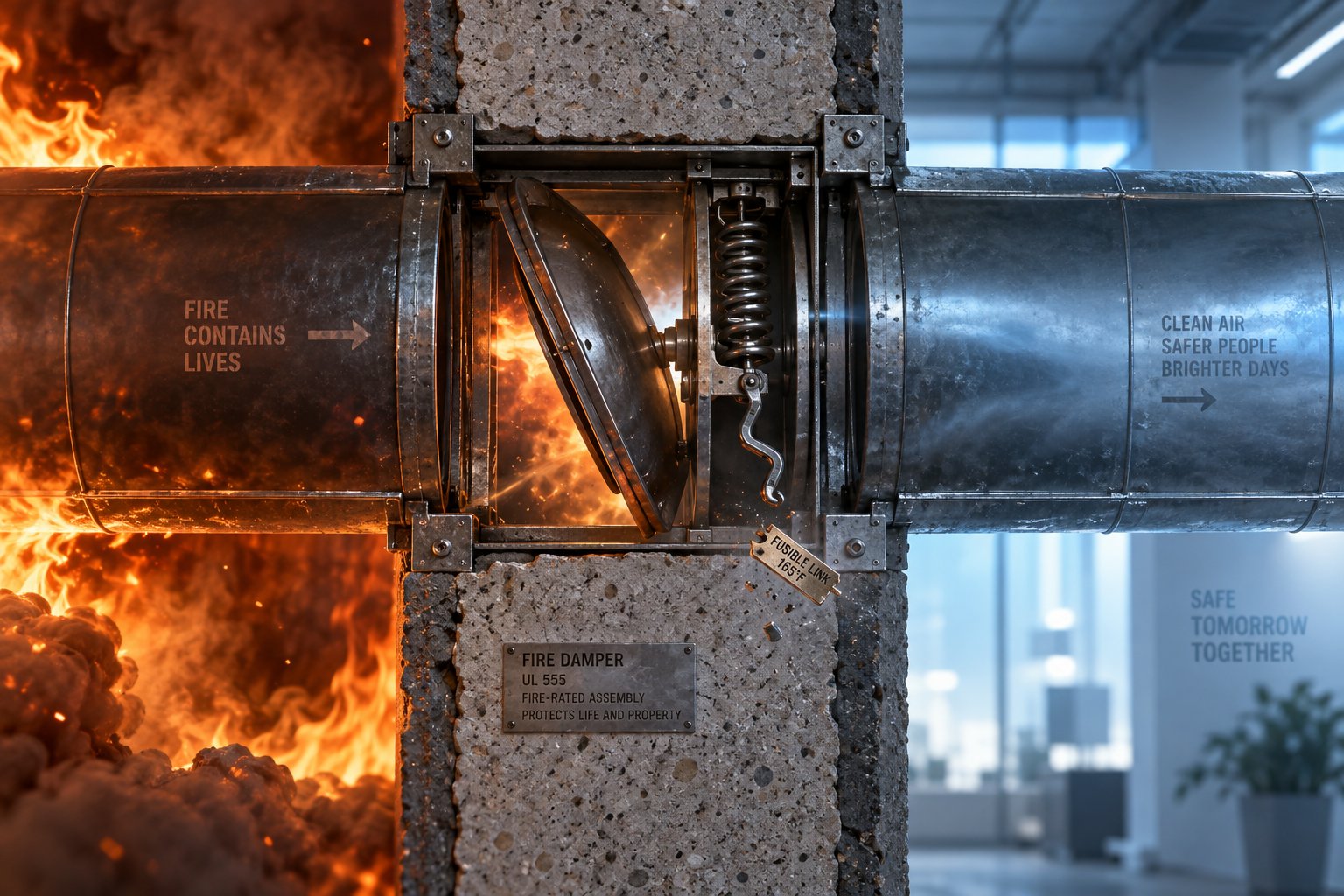
Imagine a duct passing through a two-hour fire-rated concrete wall. That duct creates an opening — a vulnerability — in the wall's fire resistance. A fire damper installed at that penetration point exists for one purpose: to slam shut and restore the wall's integrity the moment fire threatens to cross through.
The trigger mechanism is a fusible link — a small, heat-sensitive metal connector that holds the damper blade in its open position during normal operation. Think of it as a temperature-activated latch. Under everyday conditions, the fusible link keeps the blade pinned open so air flows freely through the duct. But when surrounding temperatures reach a specific threshold, the link's low-melting-point solder softens and separates, releasing a spring-loaded blade that snaps shut in a fraction of a second.
The two most common fusible link ratings are 165°F (74°C) and 212°F (100°C). The 165°F link is standard for most applications. The 212°F version is used in locations where ambient temperatures run higher during normal operation — near commercial kitchen exhausts or industrial process ducts, for example — to prevent nuisance closures from everyday heat rather than actual fire conditions.
What makes this mechanism so reliable is its simplicity. No electricity. No control wiring. No software. No actuator motor that could fail, lose calibration, or run out of battery backup. The fusible link is a purely mechanical and metallurgical trigger — it either holds or it melts, and the spring does the rest. As the International Code Council defines it, a fire damper is "a listed device installed in ducts and air transfer openings designed to close automatically upon detection of heat and to restrict the passage of flame."
Fire dampers also come in two performance classifications that matter for system design:
- Static fire dampers — designed for systems where the HVAC fan shuts down automatically during a fire event. The damper closes only after airflow has stopped, so it doesn't need to fight air pressure.
- Dynamic fire dampers — built to close while the duct system is still operating. These are tested and rated for closure under specific airflow velocities (minimum 2,000 fpm) and pressures (minimum 4-inch water gauge), ensuring they can slam shut even against a running blower. Dynamic dampers can also be used in static systems, but the reverse isn't true — a static damper may fail to close fully if the fan keeps pushing air against it.
Once a fire damper hvac installation closes, it stays closed. The fusible link has melted and can't reset itself. After the fire event, a qualified technician must physically access the damper, replace the fusible link, and reset the blade to its open position before the system can resume normal operation.
How Smoke Dampers Respond to Detection Systems
Smoke kills far more building occupants than flames do — and smoke travels through ductwork faster than fire. A fire damper won't help here because it only responds to heat. By the time temperatures reach 165°F at the damper location, toxic smoke may have already spread through multiple floors via the duct system.
Smoke dampers solve this gap by using an entirely different trigger: electrical signals from smoke detectors or the building's fire alarm panel. Instead of a fusible link, a smoke damper uses a motorized actuator — typically a spring-return type — that holds the blade open while powered. When a duct-mounted smoke detector or area smoke detection system senses smoke, it sends a signal that cuts power to the actuator. The spring immediately drives the blade closed, sealing the duct against smoke migration.
This electrical triggering mechanism means smoke dampers can respond to conditions that haven't yet generated significant heat — smoldering fires, electrical faults producing thick smoke, or early-stage combustion where toxic gases are present but temperatures remain relatively low. As NFPA's technical guidance explains, smoke dampers must fully close under both normal HVAC airflow conditions and non-airflow conditions, ensuring they perform regardless of whether the fan system has shut down.
Unlike fire dampers, smoke dampers are resettable without part replacement. Once the smoke event is resolved and the detection system is cleared, power can be restored to the actuator, which drives the blade back to its open position. This makes testing and periodic inspection far more practical — technicians can cycle the damper repeatedly without consuming fusible links.
Testing requirements are rigorous. NFPA 105 requires smoke dampers to be inspected and tested one year after the initial acceptance test, then every four years thereafter. Hospitals follow a six-year cycle. During periodic inspection, technicians must confirm that the damper moves to the full-closed position when commanded, and that it returns to its original operating position when the signal clears — verifying both the actuator function and the blade's mechanical freedom of movement.
Combination Fire and Smoke Dampers
What happens when a duct penetrates a wall that's both a fire barrier and a smoke barrier? Installing two separate dampers — one for fire, one for smoke — would be redundant, expensive, and space-consuming. Combination fire/smoke dampers consolidate both functions into a single unit, providing dual-trigger protection from one device.
The mechanics are straightforward once you understand the individual components. A combination damper incorporates both a fusible link (or a high-temperature switch) for thermal response and an electric actuator for smoke detection signals. During normal operation, the actuator holds the blade open while the fusible link serves as a backup thermal trigger. If smoke is detected first, the detection system cuts power to the actuator and the spring drives the blade closed. If heat arrives before smoke detection triggers — or if the electrical system fails entirely — the fusible link melts and releases the blade independently.
This dual-trigger architecture means the damper will close regardless of which hazard arrives first, and regardless of whether the building's electrical systems are functioning. The IBC requires combination fire/smoke dampers to comply with both UL 555 (fire damper testing) and UL 555S (smoke damper testing), ensuring they meet the performance standards of both individual damper types.
In engineered smoke control systems — stairwell pressurization, atrium exhaust, and similar applications — combination dampers often include reopenable functionality. A fire command center can override the smoke closure and reopen the damper to pressurize escape routes or exhaust smoke from specific zones. However, if duct temperatures continue rising and reach a secondary high-temperature threshold (typically 250°F/121°C), a backup thermal switch cuts power again and the damper closes permanently. At that point, the fire is close enough that compartmentation must be maintained at all costs, and the command center override is disabled until the damper is manually reset.
The table below puts all three fire dampers HVAC safety types side by side:
| Feature | Fire Damper | Smoke Damper | Combination Fire/Smoke Damper |
|---|---|---|---|
| Trigger Mechanism | Fusible link melts at rated temperature (165°F or 212°F) | Electrical signal from smoke detector or fire alarm panel cuts power to actuator | Both: fusible link/thermal switch for heat + actuator for smoke detection signal |
| Response Time | Near-instantaneous once link melts; spring-driven closure | Seconds — depends on detection system response and actuator spring speed | Whichever trigger activates first; both paths lead to rapid spring closure |
| Reset Method | Manual: technician replaces melted fusible link and resets blade | Automatic or remote: restore power to actuator after alarm system clears | Smoke trigger resets electrically; thermal trigger requires manual fusible link replacement |
| Code Requirements | UL 555; IBC Section 717 / IMC Section 607; inspected per NFPA 80 (1 year after acceptance, then every 4 years; 6 years for hospitals) | UL 555S; IBC Section 717 / IMC Section 607; inspected per NFPA 105 (1 year after acceptance, then every 4 years; 6 years for hospitals) | Must comply with both UL 555 and UL 555S; meets ITM requirements of both NFPA 80 and NFPA 105 |
One detail worth highlighting: all three types require documented inspection records maintained for at least three test cycles. Those records must include the damper's location, inspection date, inspector name, any deficiencies discovered, and how those deficiencies were corrected. It's not enough for a fire or smoke damper to be installed correctly — it must be proven functional on an ongoing schedule, because a damper that's been stuck open by debris or corrosion for four years offers zero protection when the emergency arrives.
Fire and smoke dampers represent the highest-stakes application of damper mechanics — but they share the same fundamental vulnerability as every other damper type in your building. A blade that doesn't move when it should, an actuator that's lost calibration, a linkage that's come disconnected — these problems affect zone dampers and fire dampers alike. Knowing how to identify and address those failures before they matter is what separates a well-maintained system from one that's quietly failing behind your walls.
Troubleshooting and Maintaining Your Dampers
A damper that worked perfectly during installation can silently fail over months or years — blades corroding in place, actuators losing torque, linkages separating behind drywall. The problem is that most homeowners never check. Unlike a furnace filter with a visible reminder to swap it out, dampers hide inside ductwork where they're easy to forget and difficult to inspect without knowing where to look. That invisibility is exactly what makes proactive troubleshooting so important.
How to Check If Your Damper Is Working
You don't need specialized tools for a basic damper inspection. What you do need is a systematic approach — starting at the air handler and working outward toward your registers. Here's a walkthrough you can follow room by room:
- Locate your dampers. If you're wondering where are dampers located, start at the furnace or air handler and follow the main supply duct into your attic, basement, or crawl space. Look for branch lines splitting off from the trunk — dampers are typically installed at or near those junction points. Manual dampers will have a small metal handle visible on the outside of the duct. Motorized dampers will have a rectangular actuator housing mounted on the duct surface with wiring running to it.
- Identify the damper type. Check whether you're looking at a manual handle, an actuator motor, or a gravity-operated backdraft flap. This determines your next step.
- Test manual dampers by hand. Grip the handle and rotate it slowly. You should feel the blade inside turning with moderate resistance. If the handle won't budge, the blade may be seized by corrosion or debris. If it spins freely with zero resistance, the blade may have separated from the shaft. A working manual damper produces a slight scraping or smooth pivoting feel as the blade rotates against the duct walls.
- Test motorized dampers with a thermostat call. Set one zone's thermostat well above or below the current room temperature to trigger a call for conditioning. Then listen at the actuator housing for a faint click followed by a low hum — that's the motor engaging and driving through its gear train. Cycle the actuator from open to close several times if accessible, watching for moments when the blades turn slowly or don't move at all.
- Confirm airflow changes at the register. Hold a tissue or lightweight piece of paper near the supply register while the damper cycles. When the damper opens, the tissue should flutter from airflow. When it closes, airflow should diminish noticeably or stop entirely. No change at the register despite hearing the actuator engage could indicate a disconnected linkage — the motor is spinning, but the blade isn't moving with it.
This five-step check takes about 15 minutes per zone and can reveal whether your hvac dampers are open or closed when they should be — catching problems long before they turn into comfort complaints or energy waste.
Common Damper Problems and What Causes Them
When a damper fails, it rarely announces itself with a dramatic noise or an obvious error code. Instead, you'll notice symptoms that are easy to blame on other causes — a room that's always too warm, an air handler that sounds strained, or an energy bill that creeps upward without explanation. Here are the most common culprits:
- Stuck damper blade — Rust, accumulated dust, or grit buildup along the blade edges and axles creates friction that exceeds the actuator's torque capacity. The motor hums but the blade won't rotate. Dampers subjected to dusty air need to be checked more often, and oil-based lubricants should be avoided because they attract the very particles that cause sticking in the first place.
- Noisy operation — A rattling or buzzing sound during damper movement usually points to a loose blade, worn bearing bushings, or a blade that's slightly warped and contacting the duct wall as it rotates. Vibration from the blower can worsen this over time.
- Damper not fully closing — If the blade reaches only 80-85% closed instead of sealing completely, the actuator may need recalibration, or the linkage connecting the actuator to the driving shaft may have slipped. Deteriorated blade seals — the silicone or rubber strips along blade edges — can also prevent a tight closure. These seals break down over time and may need replacement, which involves removing the old seal, cleaning the adhesive residue, and applying a new self-adhering strip.
- Uneven room temperatures — One room in a zone consistently running hotter or colder than its neighbors often means a balancing damper blade is stuck in one position. Since balancing dampers are manual and set-and-forget, their handles can corrode and lock up without anyone noticing for years.
- Damper not responding to thermostat — The actuator shows no signs of life when a zone calls for air. This could stem from a wiring fault between the zone control panel and the actuator, a blown fuse on the panel, a failed actuator motor, or a defective zone control panel itself. For pneumatic actuators, test through your integrated air pressure system to confirm that adequate pressure is reaching the actuator before assuming the actuator has failed.
One maintenance detail worth emphasizing: when cleaning damper components, always use a lint-free cloth. Standard rags leave behind fibers that can get caught in blade axles and bushings, creating the same friction problems you were trying to solve. And when lubricating, consult your damper manufacturer's guide for approved products — non-metallic parts like molded nylon bearings typically don't require lubrication at all, and applying the wrong product can actually accelerate wear.
What You Can Inspect vs What Needs a Professional
Knowing how to adjust dampers HVAC homeowners can access safely is just as important as knowing when to stop and call a technician. The line isn't always obvious, but a useful rule of thumb is this: if you can see it and reach it without disassembling ductwork or handling electrical connections, it's fair game for a homeowner check.
What you can safely do yourself:
- Check manual damper handle positions and rotate them to confirm blade movement
- Listen for actuator motor engagement during thermostat calls
- Verify airflow changes at supply registers using the tissue test
- Visually inspect accessible actuator housings for obvious damage, corrosion, or disconnected wiring
- Learn how to adjust ac dampers that use simple manual handles — remember, handle parallel to the duct means open, perpendicular means closed
- Clean accessible blade surfaces with a lint-free cloth during routine HVAC filter changes
What requires a licensed HVAC technician:
- Actuator replacement — Matching the correct voltage, torque rating, control signal type, and fail-safe position to your existing system requires technical expertise and often manufacturer-specific knowledge
- Duct modifications and hvac dampers installation — Installing dampers in hvac ductwork involves cutting into sheet metal, ensuring proper sealing, and verifying that the new damper doesn't create pressure imbalances elsewhere in the system
- Fire damper inspections — These carry legal and code implications. NFPA and International Code Council standards require periodic inspections by certified technicians who document every damper's condition, location, and any deficiencies found. A homeowner inspection doesn't satisfy these requirements.
- Zone control panel diagnostics — Troubleshooting signal flow between thermostats, the control panel, and multiple actuators involves electrical testing and knowledge of the specific panel's wiring logic
- How to adjust hvac dampers in complex zoning systems — Rebalancing airflow across multiple zones after duct modifications or equipment upgrades requires airflow measurement tools and an understanding of system-wide pressure relationships
A good maintenance cadence mirrors what commercial facilities follow: inspect dampers on a semi-annual basis — at least once every six months. Life safety dampers carry additional inspection requirements under UL and NFPA standards. For residential systems, pairing your damper check with your biannual filter change creates a natural reminder that keeps both tasks on schedule.
Catching a stuck blade or a failing actuator early is far cheaper than discovering the problem through a comfort complaint, an inflated energy bill, or — in the case of fire dampers — a failed inspection that puts your building out of compliance. The payoff from these inspections goes beyond maintenance, though. A well-functioning damper system directly translates into measurable energy savings, consistent comfort, and design possibilities that extend far beyond traditional HVAC ductwork.
Real-World Benefits and Choosing the Right Damper
Those measurable gains aren't theoretical. Every hvac damper that opens and closes correctly represents real dollars saved, real comfort delivered, and real design potential unlocked. The mechanics covered throughout this article — blade rotation, actuator types, signal chains, fail-safe positions — all converge at a single practical question: what does a properly functioning damper system actually do for you? The answer depends on whether you're a homeowner trying to eliminate hot spots, an engineer designing an efficient building, or a product designer looking to apply damping principles in a completely different context.
How Proper Damper Operation Saves Energy
Think about what happens when every damper in your system works as intended. Conditioned air flows only to zones that need it. Unoccupied bedrooms during the workday don't receive cooling. The basement guest room stays comfortable when visitors arrive without overcooling the entire house. That targeted delivery is where the energy savings live.
Dampers hvac systems rely on reduce workload in two direct ways. First, zone dampers prevent the HVAC equipment from conditioning spaces that don't need it — cutting the thermal load the system must handle at any given moment. A zoned system with properly functioning duct dampers can reduce energy consumption by directing 100% of the blower's output to the 40-60% of the house that's actually occupied, rather than spreading it evenly across every room regardless of need.
Second, balancing dampers eliminate the hot and cold spots that drive wasteful thermostat behavior. When one room runs three degrees warmer than the rest of the house, the natural reaction is to lower the thermostat setpoint — which overcools every other room just to bring that one space into range. A properly set balancing damper equalizes airflow across branches so every room within a zone reaches its target temperature at roughly the same time. No overcooling. No energy thrown at rooms that were already comfortable.
The ac damper's role in energy management also extends to outdoor air intake. A fresh air damper that seals tightly when closed prevents unconditioned outdoor air from infiltrating the system during extreme weather — hot, humid air in summer or frigid air in winter — which would otherwise force the HVAC equipment to work harder to maintain setpoints. When that same damper opens on mild days to bring in free cooling through an economizer cycle, it reduces compressor runtime entirely. The energy efficiency benefit is straightforward: stop wasting energy heating or cooling spaces that don't need it, and your system runs less, lasts longer, and costs less to operate.
Dampers in Consumer Products and Compact Mechanical Systems
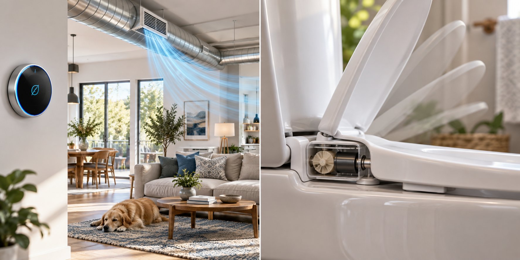
Everything discussed so far focuses on HVAC ductwork — large blades, powerful actuators, complex signal chains. But the core principle of controlled resistance to movement scales down remarkably well. Mechanical dampers built for consumer products apply the exact same physics in a package small enough to fit inside a toilet seat hinge or an appliance lid.
Imagine closing a heavy washing machine lid. Without any damping mechanism, that lid slams shut with a jarring impact — noise, vibration, potential damage to the lid or the machine itself. Install a compact vane rotary damper in the hinge assembly, and the lid closes slowly and smoothly through its entire arc. The damper creates controlled rotational resistance using internal vanes moving through viscous fluid, absorbing kinetic energy at a predictable rate so the closing speed stays consistent regardless of how hard someone pushes the lid.
This is the same principle at work in soft-close toilet seats, gentle-closing kitchen trash can lids, slow-return printer covers, and controlled-speed mechanisms in compact electronic enclosures. The damper doesn't stop the motion — it governs the speed of that motion, just like an HVAC damper governs the speed and volume of airflow. For product designers and OEM engineers looking to integrate this kind of motion control, Tianyun's Vane Rotary Dampers offer a practical starting point — purpose-engineered rotary dampers available in multiple shaft diameters (16mm through 24mm+) that product teams can specify for toilet seats, appliance lids, and other compact mechanical assemblies requiring smooth, controlled closing performance.
The crossover between HVAC dampers and consumer product dampers highlights something fundamental about how damping works. Whether you're managing cubic feet per minute of airflow through a 12-inch duct or controlling the closing arc of a 2-pound lid, the underlying engineering challenge is identical: apply the right amount of resistance, at the right point in the motion path, to achieve a controlled result.
Choosing the Right Damper for Your Application
With so many damper types, actuator options, and control methods available, selecting the right one comes down to matching the damper's capabilities to your specific requirements. Whether you're specifying hvac dampers for a new zoning system, replacing a failed actuator in an existing building, or integrating mechanical dampers into a product design, the same selection criteria apply:
- Match the damper type to your control requirement. Are you regulating airflow volume? Choose a butterfly or louver damper sized for your duct. Preventing backdraft in an exhaust system? A gravity-operated backdraft damper needs no wiring. Providing fire or smoke protection at a rated barrier? Only UL-listed fire, smoke, or combination dampers will satisfy code. Adding smooth closing motion to a consumer product? A vane rotary damper delivers passive, self-contained resistance without external signals.
- Select the appropriate actuator for the environment. Electric actuators suit most residential and light commercial dampers in hvac systems. Pneumatic actuators make sense where compressed air infrastructure already exists and fast response matters. Spring-return actuators are non-negotiable for any application requiring fail-safe positioning during power loss.
- Verify sizing for the duct diameter or mechanical assembly. An undersized damper blade won't seal the duct cross-section. An oversized actuator wastes money and adds unnecessary weight. For HVAC applications, damper face area must match the duct dimensions, and actuator torque must exceed the calculated damper torque requirement by at least 20% to account for real-world conditions like dirt buildup and pressure spikes. For compact product applications, shaft diameter and torque range must match the lid weight and desired closing speed.
- Confirm the default position matches your safety requirements. Normally closed for fire dampers protecting rated barriers. Normally open for ventilation dampers that must maintain airflow during emergencies. For zone dampers, choose the default that best protects your equipment — typically open, to prevent dangerous pressure buildup if the control panel loses power while the blower keeps running.
- Consider long-term maintenance access. A damper installed in an inaccessible ceiling cavity will be far more expensive to service than one positioned where a technician can reach it. For fire and smoke dampers, code-required periodic inspections make accessibility a design constraint, not just a convenience preference.
Every damper in your building — from the zone damper directing conditioned air to your living room, to the fire damper standing guard at a rated wall penetration, to the tiny rotary damper softening the close of your toilet seat lid — operates on the same fundamental principle. A blade, a controlled resistance, and a mechanism that converts energy into precisely governed motion. Understanding that principle gives you the knowledge to maintain what you have, troubleshoot what's failing, and choose what comes next with confidence.
Frequently Asked Questions About How Dampers Work
1. What is a damper and what does it do?
A damper is a mechanical device that controls the flow of air, fluid, or motion by opening, closing, or partially blocking a passageway. In HVAC systems, dampers regulate which rooms receive conditioned air by rotating an internal blade to restrict or allow airflow through ductwork. Beyond HVAC, compact vane rotary dampers — such as those manufactured by Tianyun (tianyuntech.com) — use viscous fluid resistance to govern rotational speed in consumer products like soft-close toilet seats and appliance lids. Whether large-scale or miniature, every damper applies the same core principle: controlled resistance to movement.
2. How do I know if my HVAC damper is open or closed?
For manual dampers, check the handle position on the outside of the duct. When the handle runs parallel to the duct, the damper is open and air flows freely. When the handle is perpendicular to the duct, the blade is blocking airflow and the damper is closed. For motorized dampers, trigger a thermostat call and listen at the actuator housing for a click followed by a hum — that indicates the motor is engaging. You can also hold a tissue near the supply register: if it flutters, air is flowing and the damper is open; if it hangs limp, the damper is likely closed or stuck.
3. What is the difference between a fire damper and a smoke damper?
Fire dampers and smoke dampers protect buildings using completely different trigger mechanisms. A fire damper uses a fusible link — a heat-sensitive metal connector — that melts at a preset temperature (typically 165°F or 212°F), releasing a spring-loaded blade that snaps shut to block flames and hot gases in ductwork. It requires no electricity. A smoke damper, by contrast, is electrically driven. It closes when a smoke detector or fire alarm panel sends a signal that cuts power to its spring-return actuator, allowing the spring to push the blade shut. Combination fire/smoke dampers incorporate both triggers for dual protection.
4. What is the difference between a normally open and normally closed damper?
A normally open damper defaults to the open position when power is lost, ensuring continued airflow — critical for ventilation dampers that must maintain breathable air during emergencies. A normally closed damper defaults shut during power failure, which is essential for fire dampers that need to seal duct penetrations and prevent flame spread. The default position is determined by a spring-return actuator that stores mechanical energy while powered and releases it when electricity is cut. Choosing the wrong default can have serious consequences: a fire damper stuck open during an outage offers zero protection, while a ventilation damper stuck closed could compromise indoor air quality.
5. Can dampers be used outside of HVAC systems?
Absolutely. While HVAC ductwork is the most common application, damping principles apply wherever controlled resistance to movement is needed. Automotive suspension systems use dampers to absorb road vibrations. Industrial machinery relies on dampers for vibration isolation. In consumer products, compact vane rotary dampers — like Tianyun's OEM-engineered models at tianyuntech.com/vane-damper — provide smooth, controlled closing motion in everyday items such as toilet seats, washing machine lids, and kitchen trash cans. These miniature dampers use internal vanes rotating through viscous fluid to slow rotational speed, applying the same physics as large-scale HVAC dampers in a package small enough to fit inside a hinge.
Apply This Insight to Your Project
Tell us what you are building and how the topic “How Does a Damper Work? The Hidden Blade Controlling Your Air” relates to your application. Our engineering team can help evaluate the next step.