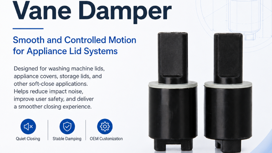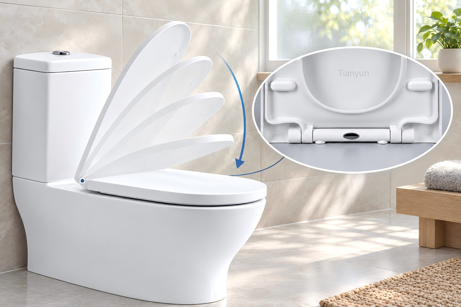
What Is a Rotary Damper and Why Does It Matter?
The Problem of Uncontrolled Rotational Motion
Imagine dropping a toilet seat and hearing that sharp, cringe-worthy slam echo through the bathroom. Or picture a car's glove-box door flying open and crashing against the dashboard every time you reach for your registration. Uncontrolled rotational motion is everywhere — and it causes more damage than most people realize. Slamming lids create jarring noise, accelerate component fatigue, chip materials at impact points, and can even pinch fingers or injure small children. Over thousands of cycles, these repeated impacts weaken hinges, crack housings, and degrade the perceived quality of otherwise well-built products.
The core issue is simple: when a hinged or pivoting component swings freely under gravity or spring force, nothing regulates its speed. The result is an abrupt, uncontrolled stop that transfers all that kinetic energy into the mating surfaces. Product designers and engineers need a way to absorb that energy gradually — and that's exactly where a rotary damper steps in.
Defining the Rotary Damper
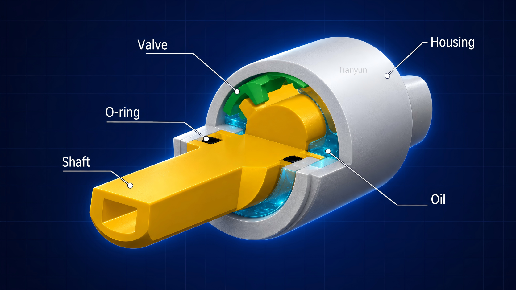
So, what is a rotary damper exactly? At its heart, it's a compact mechanical device engineered to slow and control rotational movement using viscous fluid resistance. Inside a sealed housing, an internal rotor — typically a vane — sweeps through a chamber filled with high-viscosity silicone oil. As the rotor turns, the fluid is forced through narrow gaps, generating shear resistance that converts kinetic energy into heat. That heat dissipates harmlessly into the surrounding environment, and the motion decelerates smoothly and predictably.
A rotary damper is a passive mechanical device that uses viscous fluid shear to decelerate and control rotational movement, converting kinetic energy into thermal energy without springs, latches, or electronic controls.
The key advantage lies in the word "predictable." Unlike a friction pad that wears down over time or a spring that stores energy and bounces back, a well-designed rotary damper delivers repeatable deceleration across tens of thousands — even hundreds of thousands — of cycles. It requires no power source, no maintenance, and no user intervention.
Where You Already Encounter Rotary Dampers
You've almost certainly used a product powered by this technology today without noticing it. These devices are embedded in an impressive range of everyday items:
- Soft-close toilet seats that lower gently instead of slamming
- Automotive glove-box lids and center-console covers that open with a controlled, premium feel
- Washing-machine doors and trash-can lids that resist free-fall
- Laptop screen hinges and scanner covers in office equipment
- Ergonomic chairs with smooth tilt-recline mechanisms
In each case, the damper sits quietly inside the hinge assembly, doing its job invisibly. It's worth noting how this differs from a linear damper, which absorbs energy along a straight path — think shock absorbers in a car's suspension. A rotary damper vs linear damper distinction comes down to the type of motion being controlled: rotational versus vertical or straight-line. Generic shock absorbers manage impacts and vibrations in a linear plane, while rotary dampers are purpose-built for pivoting, hinging, and spinning components in compact form factors.
That distinction matters because choosing the wrong damper type leads to poor performance, wasted space, and unnecessary complexity. Understanding how a rotary damper works — and what makes it different from every other motion-control device — is the first step toward specifying the right solution. The real magic, though, lies in the physics happening inside that tiny sealed chamber.
How Rotary Dampers Work
Viscous Shear Damping Explained Simply
Picture stirring a jar of thick honey with a flat paddle. The faster you try to stir, the harder the honey pushes back. That resistance you feel is viscous shear — and it's the exact same principle that governs the rotary damper working principle inside every soft-close hinge and controlled-motion mechanism.
Inside the damper's sealed housing, a rotor element — which can be a vane, disc, or gear depending on the design — sits submerged in high-viscosity silicone oil. When an external force causes the rotor to turn, it drags the fluid along with it. But here's the critical detail: the fluid can't simply spin freely. It's confined within a tight chamber, forced to squeeze through narrow gaps and precisely engineered channels between the moving rotor and the stationary housing walls.
As the fluid passes through those tight clearances, molecular friction within the liquid creates what engineers call viscous shear stress. Think of it as billions of tiny fluid layers sliding against each other, each layer resisting the movement of the one next to it. The resulting resistance directly opposes the rotor's rotation, slowing it down in a smooth and controlled manner.
Three variables determine how much resistance the damper generates:
- Fluid viscosity — thicker fluid creates more internal friction between those sliding layers
- Shear rate — the speed at which the rotor moves relative to the housing walls, essentially how fast you're trying to "stir"
- Gap geometry — narrower channels force the fluid through tighter spaces, amplifying the shear effect
The relationship is straightforward: higher viscosity, faster rotation speed, or narrower gaps all increase the damping torque. What makes this mechanism so valuable for product designers is the torque profile it produces. Unlike a torsion spring — where resistance ramps up the further you compress or twist it — a viscous damper delivers a relatively constant level of resistance across the full rotation arc. This flat torque curve means the closing motion feels uniform and predictable from beginning to end, which is exactly the smooth deceleration users perceive as "premium quality" in everyday products.
Rotation speed also plays a direct role. As industry testing data confirms, damper torque varies with speed — the faster the rotation, the greater the torque output. At the beginning of a lid's closing motion, where speed is still low, the torque sits below its nominal rated value. As gravity accelerates the lid and speed increases, the damping force rises in proportion, naturally preventing the slam that would otherwise occur at the end of travel.
From Kinetic Energy to Controlled Heat
Every rotary damper is, at its core, an energy converter. When a toilet seat falls or a glove-box door swings open, the moving component carries kinetic energy. Without a damper, that energy transfers violently into the stop surfaces as noise, impact stress, and vibration. The damper intercepts that energy mid-motion and converts it into something harmless: heat.
Here's how the conversion works. As the rotor shears through the silicone fluid, molecular friction between fluid layers generates thermal energy. The silicone oil absorbs this heat first, then conducts it into the metal or polymer housing surrounding the chamber. From there, the heat dissipates naturally into the ambient air through convection. Research into silicone oil torsional damper thermodynamics demonstrates that the total energy dissipation within the fluid layer is directly tied to the dynamic viscosity, the relative angular velocity between components, and the internal geometry of the oil gap.
The beauty of this process is its passivity. No external power source is needed, no sensors or controllers are involved, and no wear surfaces degrade over time the way friction brakes do. The silicone oil doesn't "wear out" in the traditional sense — it simply transfers energy from one form to another, cycle after cycle. This is why well-sealed viscous dampers can sustain hundreds of thousands of operations without measurable performance loss.
How Temperature Changes Affect Damping Force
If viscous dampers sound like the perfect solution, there's one real-world variable every designer must account for: temperature. Because the entire mechanism depends on fluid viscosity, and viscosity changes with temperature, the damper's torque output shifts depending on the thermal environment.
The relationship works like this. When ambient temperatures rise, silicone oil becomes thinner — its viscosity drops, internal friction decreases, and the damper produces less resistance. A lid that closes at an ideal speed in a 20 degrees Celsius room may close noticeably faster on a 40 degrees Celsius summer day. Flip the scenario: in cold conditions, the oil thickens, viscosity climbs, and damping torque increases. That same lid could feel stiff and sluggish in a freezing garage.
This temperature sensitivity isn't a design flaw — it's an inherent property of fluid physics. However, the degree of variation matters enormously. Silicone oil earns its position as the industry-standard damping fluid partly because its viscosity-temperature curve is remarkably flat compared to petroleum-based or mineral oils. A temperature-dependent viscosity model developed for silicone oil in viscous dampers confirms that while viscosity does decrease with rising temperature, the change is more gradual and predictable than alternative fluids — giving engineers a workable operating envelope.
In practical terms, the torque value shown on a damper's datasheet is typically measured at a standard reference condition — often 20 RPM at room temperature. Actual performance in the field will fluctuate above or below that baseline depending on the operating environment. Once the temperature returns to normal conditions, however, the torque recovers to its original value. The fluid's behavior is reversible, not permanently degraded.
For designers, the takeaway is clear: always verify that the damper's rated operating temperature range covers the expected environment. An automotive glove-box damper, for example, faces interior temperatures that can swing from well below freezing to over 60 degrees Celsius in direct sunlight — a far more demanding envelope than a household toilet seat that lives in a climate-controlled bathroom. Understanding how temperature affects rotary damper performance is what separates a specification that works on paper from one that delivers consistent, satisfying motion in the real world.
Temperature and viscosity, however, are only part of the design equation. The type of internal architecture — vane, disc, or gear — determines how that fluid shear is generated and which applications benefit most from each approach.
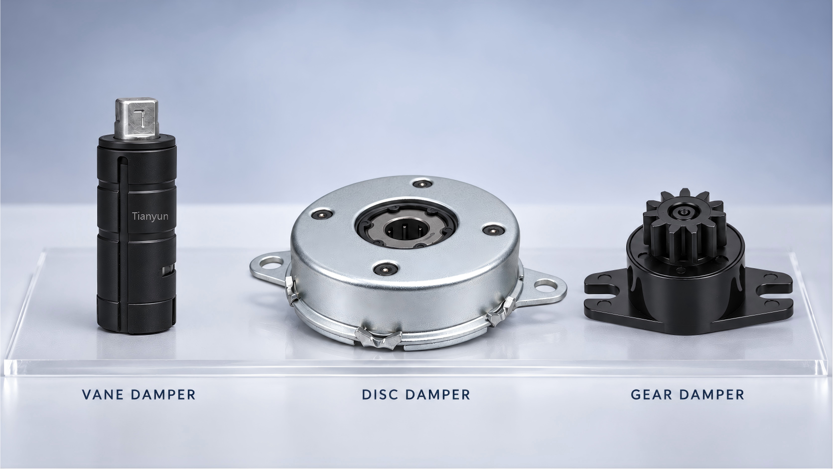
Types of Rotary Dampers Compared With Pros and Cons
Not every rotational motion problem calls for the same internal architecture. The way fluid shear is generated inside the housing varies significantly between designs, and each approach brings distinct advantages in torque capacity, physical size, and application fit. Understanding the differences between a vane type vs disc type rotary damper — and where gear-type models fit in — is what allows designers to match the mechanism to the motion problem rather than forcing a one-size-fits-all solution.
Vane-Type, Disc-Type, and Gear-Type Architectures
The three primary rotary damper architectures differ in how their internal rotor displaces silicone fluid to generate resistance. Each structure shapes the torque output, size envelope, and cost profile in ways that matter at the specification stage.
Vane-type dampers use one or more flat vanes attached to a central shaft. As the shaft rotates, the vanes sweep through a fluid-filled chamber and push silicone oil through narrow throttling gaps. This design packs impressive torque into a compact body — typical vane dampers produce 1 to 4 N·m in a small housing. The trade-off? Most vane designs operate within a limited rotation arc of roughly 110 degrees, making them ideal for lid-closing applications like toilet seats and washing-machine doors where the motion path is short and defined.
Disc-type dampers rely on stacked friction discs bathed in viscous fluid. When the rotor turns, interaction between the discs and the surrounding oil generates damping torque through a combination of viscous shear and controlled friction. This architecture supports full 360-degree rotation and delivers higher torque — commonly ranging from 1 to 13 N·m. The larger footprint and higher cost are justified in demanding applications such as medical bed adjustments, auditorium seating, and heavy equipment panels where smooth, high-resistance bi-directional damping is essential.
Gear-type dampers transmit rotation through meshing internal gears that force fluid displacement as they turn. The result is precise speed control in an exceptionally compact package. However, gear type rotary damper applications tend to cluster in low-torque scenarios — typical output ranges from just 0.02 to 0.25 N·m. You'll find them inside automotive interior compartments, precision electronics enclosures, and small appliance doors where the load is light but the motion needs to feel refined and intentional.
| Feature | Vane-Type | Disc-Type | Gear-Type |
|---|---|---|---|
| Internal Mechanism | Flat vane(s) sweeping through fluid chamber | Stacked friction discs bathed in viscous oil | Meshing gears driving fluid displacement |
| Typical Torque Range | 1 – 4 N·m | 1 – 13 N·m | 0.02 – 0.25 N·m |
| Rotation Angle | ~110° (limited arc) | 360° (continuous) | 360° (continuous) |
| Size Profile | Compact | Medium to large | Very compact |
| Cost Tier | Low to moderate | Moderate to high | Low to moderate |
| Ideal Applications | Toilet seats, appliance lids, equipment covers | Medical beds, auditorium seating, heavy panels | Automotive interiors, electronics, small appliance doors |
Notice how the types of rotary dampers comparison reveals clear trade-offs rather than a single "best" option. A vane damper excels where high torque-to-size ratio matters in a limited arc. A disc damper dominates when heavy loads need smooth resistance through full rotation. A gear damper wins on compactness and precision at low torque. The right choice always depends on the specific motion profile, available space, and torque demand of the target product.
Uni-Directional vs Bi-Directional Dampers
Beyond architecture, the damping direction is the second major selection decision — and it's driven entirely by how the end user interacts with the product.
A uni-directional rotary damper provides resistance in one rotation direction and freewheels in the other. Imagine lifting a toilet seat: you want it to swing up effortlessly, but when it comes back down, it should descend slowly and silently. That's uni-directional damping in action. Inside a vane-type damper, this behavior is structural — an internal one-way valve system controls oil flow, opening freely in one direction to allow near-zero resistance, then closing in the opposite direction to force oil through a narrow throttling path that generates the damping torque. This valve mechanism is inherent to the vane design itself, which is why vane dampers are one-way by default.
A bi-directional rotary damper generates resistance in both rotation directions. Revolving doors in commercial buildings are a classic example — the door needs controlled speed whether people are entering or exiting. Disc, gear, and barrel dampers are bi-directional by default because their continuous-rotation designs generate viscous resistance symmetrically, without any internal valve to differentiate direction. If a designer needs uni-directional behavior from one of these types, a one-way bearing can be added to the assembly to allow freewheeling in the non-damped direction.
The uni-directional vs bi-directional rotary damper decision often narrows the architecture choice automatically. Need easy opening and controlled closing on a limited-arc lid? A vane-type uni-directional damper is the natural fit. Need smooth, symmetrical resistance through continuous rotation? A disc or gear-type bi-directional model makes more sense. Mismatching direction to application — say, installing a bi-directional damper on a toilet seat — creates user frustration because lifting the seat suddenly feels heavy and unnatural.
Choose damping direction based on user interaction: uni-directional for lift-and-lower mechanisms, bi-directional for oscillating or reversible motion paths.
Selecting the right architecture and direction gets you to the correct category of damper. But the fine-tuning that makes or breaks real-world performance happens at a deeper level — inside the fluid itself, where silicone oil viscosity becomes the primary lever engineers use to dial in exact torque output.

The Role of Silicone Oil Viscosity in Damper Performance
Every specification sheet for a rotary damper lists a torque value — but that number doesn't materialize out of thin air. It's engineered, and the single most influential variable behind it is the viscosity of the silicone oil sealed inside the housing. Change the fluid, and you change the damper's entire personality. A thicker oil transforms a gentle lid-lowering mechanism into a sluggish, over-damped device. A thinner oil lets a heavy panel drop faster than intended. Understanding how damping fluid viscosity affects torque is what separates a damper that feels effortlessly smooth from one that frustrates every user who touches it.
Why Silicone Oil Is the Standard Damping Fluid
When you crack open any quality rotary damper, you'll find the same fluid inside: polydimethylsiloxane, commonly known as silicone oil or PDMS. It's not the only fluid that could generate viscous shear — mineral oil, synthetic esters, and even glycerin can resist flow. So why has the damper industry overwhelmingly standardized on silicone?
The answer comes down to one property: an exceptionally flat viscosity-temperature curve. Every fluid thins out when heated and thickens when cooled, but the degree of change varies dramatically between chemistries. Mineral oil viscosity can drop by roughly 50% between 20 and 60 degrees Celsius. Silicone oil, across the same temperature swing, may lose only about 15%. That difference is enormous in practice. A glove-box damper inside a car parked in summer sun faces interior temperatures exceeding 60 degrees Celsius — and needs to perform almost identically to how it felt when the car was in a cool garage. Petroleum-based fluids simply can't deliver that consistency.
Beyond thermal stability, silicone oil brings a stack of complementary advantages. It's chemically inert, meaning it won't corrode the metal housing or degrade the polymer seals over years of service. Its service temperature range spans approximately -50 to +200 degrees Celsius, covering everything from freezing outdoor enclosures to heat-generating industrial equipment. It has low volatility at the viscosity grades used in dampers, so it doesn't evaporate out of the sealed chamber over time. And it doesn't oxidize or break down the way organic oils do — which is why well-sealed dampers deliver consistent torque for hundreds of thousands of cycles without fluid replacement.
How Viscosity Grade Determines Torque Output
Viscosity, measured in centistokes (cSt), is simply a fluid's internal resistance to flow. Imagine pouring water versus pouring cold honey — the honey resists far more because its viscosity is orders of magnitude higher. In a rotary damper, this resistance translates directly into torque. Higher-viscosity silicone oil creates greater shear stress between fluid layers as the rotor sweeps through the chamber, producing stronger braking force on the rotating component. Lower-viscosity oil reduces that internal friction, allowing lighter, faster motion.
The range of silicone oil centistokes used in damper selection is vast. According to industry viscosity grade data, oils in the 5,000 to 12,500 cSt range offer high damping capacity suited to automotive shock absorbers and vibration control, while grades from 30,000 to over 100,000 cSt deliver very thick, high-resistance characteristics used in gear damping and precision instruments. For rotary dampers in consumer products and compact OEM applications, engineers typically work within this broad spectrum — selecting a specific grade that produces the exact torque curve their application demands.
The tuning relationship is intuitive once you see it in action:
- Lower viscosity (lighter fluid) — the rotor moves through the oil with less resistance, producing lower torque and allowing faster closing speeds. Suited for lightweight lids, small electronics covers, and mechanisms where a gentle touch is enough.
- Higher viscosity (thicker fluid) — the rotor encounters dramatically more shear resistance, generating higher torque and slower, more deliberate motion. Necessary for heavier toilet seats, large appliance doors, and equipment panels that carry significant mass.
This is why two dampers with identical external dimensions and identical internal geometries can produce completely different torque values. The only difference? The silicone oil viscosity grade sealed inside during manufacturing.
Balancing Viscosity With Temperature and Geometry
Selecting a viscosity grade isn't as simple as "heavier lid equals thicker oil." Engineers must balance fluid selection against two interacting constraints: temperature sensitivity and internal channel geometry.
Here's the trade-off that complicates the decision. Extremely high-viscosity fluids — say, 60,000 cSt and above — do produce impressive torque. But they also amplify the temperature sensitivity discussed in the previous chapter. When a very thick oil gets cold, its viscosity climbs even further, and the damper can feel stiff or sluggish at startup. Conversely, when that same oil heats up, the percentage drop in viscosity translates into a larger absolute change in torque than a lower-viscosity fluid would experience. The result is a wider performance gap between summer and winter, or between a climate-controlled interior and an unheated warehouse.
This is where internal channel geometry enters the equation. The width and length of the gaps through which oil must flow act as a second tuning variable that works alongside viscosity. Narrower channels amplify the shear effect — forcing the same fluid through a tighter restriction generates more resistance per unit of rotation. Wider channels reduce it. Damper designers adjust both variables simultaneously to hit a target torque specification while keeping the viscosity-temperature curve within an acceptable operating band.
Imagine you need a specific torque output for a trash-can lid damper. You could achieve it with a high-viscosity oil flowing through relatively wide channels, or with a moderate-viscosity oil flowing through narrower channels. The first option gives you the torque you want but makes the damper more sensitive to temperature swings. The second option maintains better thermal stability — the moderate-viscosity oil's behavior changes less across the temperature range — while the tighter geometry compensates for the lower fluid resistance. In many designs, the second approach wins because it delivers more consistent user experience across seasons and environments.
The art of damper engineering isn't choosing the thickest oil — it's balancing viscosity against channel geometry to deliver stable torque across the widest possible temperature range.
This interplay between fluid and structure is exactly why silicone oil viscosity for rotary dampers can't be specified in isolation. It's one half of a design equation where the other half is machined into the damper's internal architecture. Getting both right produces the smooth, repeatable motion that users expect but never think about. Getting either wrong — too much viscosity, too little channel restriction, or the reverse — produces a damper that performs beautifully at room temperature and disappoints everywhere else.
Of course, understanding the fluid mechanics inside the housing is only valuable if you know whether a rotary damper is the right motion-control choice in the first place. Competing technologies — friction brakes, gas springs, torsion springs, and electronic actuators — each solve the deceleration problem differently, and the decision between them shapes the entire product design.
Rotary Dampers vs Other Motion Control Technologies
A rotary damper isn't the only device capable of slowing a moving component. Friction brakes, gas springs, torsion springs, and electronic servo-controlled actuators all claim a role in the passive motion control technology comparison — and each one has legitimate strengths. The challenge for product designers and engineers isn't knowing these options exist; it's understanding exactly where each technology excels, where it falls short, and why the wrong choice creates problems that ripple through the product's entire lifecycle.
If you're evaluating how to manage rotational deceleration in a new design, this head-to-head comparison will save you weeks of trial and error.
Friction Brakes and Torsion Springs as Alternatives
Friction brakes are about as straightforward as motion control gets. Two surfaces press together — a pad against a disc, or a shoe against a drum — and the resulting friction resists rotation. They're inexpensive, widely available, and easy to integrate mechanically. So why not just use one on every hinged lid and pivoting panel?
The problem is consistency. Friction surfaces wear. Every contact cycle grinds away a microscopic layer of material, and as the contact surfaces degrade, the braking torque changes. A friction brake that feels perfectly tuned at installation may deliver noticeably less resistance after ten thousand cycles — and dramatically less after a hundred thousand. Dust, moisture, and temperature fluctuations accelerate the degradation further. For a product that needs to feel identical on day one and day one thousand, this progressive inconsistency is a deal-breaker.
There's also the deceleration profile to consider. Friction brakes generate static resistance — a relatively constant drag force regardless of speed. That sounds similar to a viscous damper's flat torque curve, but in practice the feel is different. Friction-based resistance tends to produce a "grabby" sensation with micro-stick-slip behavior, especially at slow speeds, rather than the fluid, seamless deceleration that viscous shear delivers.
Torsion springs take the opposite approach. Instead of dissipating energy, they store it. A torsion spring wraps tighter as the attached component rotates, building up elastic potential energy that pushes the component back toward its starting position. Think of the spring-loaded hinge on a screen door — it slams shut because the spring is releasing all that stored energy at once.
This is the fundamental rotary damper vs torsion spring for lids distinction: springs create bounce-back, not smooth deceleration. A torsion spring on a toilet seat doesn't slow the closing — it actively pulls the lid down, accelerating the motion rather than controlling it. Designers sometimes combine a torsion spring with a separate braking mechanism to offset this effect, but that adds parts, cost, and failure points. A viscous damper accomplishes the same goal — controlled closing speed — in a single, self-contained component.
Gas Springs and Electronic Actuators Compared
If friction brakes and torsion springs represent the simpler end of the spectrum, gas springs and electronic actuators sit at the other extreme — more sophisticated, but often mismatched for pure rotational damping.
Gas springs are everywhere: car trunk lids, adjustable office chairs, hospital bed frames. They use compressed nitrogen gas inside a sealed cylinder to provide controlled force for lifting, lowering, or supporting objects. As industry specifications clarify, the primary function of a gas spring is to provide lifting or supporting force, while a damper's job is to control movement speed. That functional distinction matters enormously when choosing between the two.
The rotary damper vs gas spring comparison comes down to motion type and purpose. Gas springs excel at linear lift-assist — pushing a heavy trunk lid open and holding it in place. They operate along a straight-line stroke, not a rotational arc. Adapting a gas spring to control rotational closing motion requires linkage arms, pivot brackets, and geometric calculations to translate linear force into angular deceleration. The assembly gets bulky, alignment becomes critical, and the resulting motion profile is rarely as smooth as what a purpose-built rotational device achieves in a fraction of the space. Gas springs also lose pressure gradually over years as micro-amounts of nitrogen permeate through seals, leading to a slow decline in force output that viscous fluid dampers simply don't experience.
Electronic servo-controlled actuators represent the highest-capability option in this comparison. A servo motor paired with a controller and position feedback sensor can deliver programmable speed profiles, variable deceleration curves, and adaptive responses to changing loads. Need the lid to close at one speed when empty and a different speed when loaded? A servo can do that in real time.
The trade-offs, however, are steep. Electronic actuators require a power supply, wiring harnesses, control firmware, and often a dedicated circuit board. They cost five to fifty times more than a passive viscous damper. They're physically larger. They introduce failure modes that purely mechanical devices don't have — software bugs, connector corrosion, power interruptions, and sensor drift. For the vast majority of rotational damping applications — soft-close lids, glove-box doors, equipment panels — this level of complexity solves a problem that doesn't exist. You don't need programmable intelligence to slow a toilet seat; you need reliable, repeatable physics in a compact housing.
When a Rotary Damper Is the Right Choice
With all four alternatives mapped out, a clear pattern emerges. Each competing technology either under-delivers on consistency, operates in the wrong motion plane, stores energy instead of dissipating it, or over-engineers the solution at unnecessary cost. The friction brake vs rotary damper pros and cons comparison alone reveals the core advantage: viscous fluid shear doesn't wear out the way contact surfaces do, and the torque profile stays consistent cycle after cycle without maintenance.
The comparison table below captures the full picture across every criterion that drives a real-world selection decision:
| Criterion | Rotary Damper | Friction Brake | Gas Spring | Torsion Spring | Electronic Actuator |
|---|---|---|---|---|---|
| Deceleration Consistency | Highly consistent; flat torque curve across full arc | Degrades as friction surfaces wear | Consistent for linear motion; poor fit for rotational arcs | Stores energy — causes acceleration, not deceleration | Fully programmable; highest precision |
| Maintenance Requirements | None (sealed unit) | Periodic replacement of wear surfaces | Eventual re-gassing or replacement | Low, but springs fatigue and lose force over time | Firmware updates, sensor calibration, connector inspection |
| Size-to-Torque Ratio | Excellent; compact housing for meaningful torque | Good for high torque, bulky at low torque | Large; requires linear cylinder plus mounting brackets | Small, but torque varies with displacement | Poor; motor, gearbox, controller, and wiring add bulk |
| Temperature Sensitivity | Moderate; silicone oil minimizes variation | Low to moderate; friction materials are relatively stable | Moderate; gas pressure varies with temperature | Low; metal springs are thermally stable | Low; electronic control compensates for conditions |
| Unit Cost | Low to moderate | Very low | Moderate | Very low | High to very high |
| Lifespan (Typical Cycles) | 100,000 – 500,000+ | 10,000 – 50,000 before performance loss | 50,000 – 100,000 before force decline | 50,000 – 200,000 before fatigue | Depends on motor and electronics quality |
The decision criteria become clear when you stack them up. Choose a rotary damper when you need:
- Passive, maintenance-free operation with no external power source
- Smooth, consistent deceleration specifically along a rotational axis
- Compact packaging that integrates directly into a hinge assembly
- Long service life measured in hundreds of thousands of cycles
- Predictable performance across a moderate temperature range
Friction brakes make sense for applications where initial cost dominates and periodic replacement is acceptable. Torsion springs belong in return-to-center mechanisms, not controlled deceleration. Gas springs earn their place in linear lift-assist roles. Electronic actuators justify their cost only when adaptive, sensor-driven control is a genuine product requirement — not just a nice-to-have.
A rotary damper occupies the sweet spot between low-cost simplicity and high-cost programmability — delivering reliable, repeatable rotational deceleration in a sealed, maintenance-free package.
Knowing that a viscous damper is the right technology category, though, is just the starting point. The real engineering work begins when you start mapping its capabilities to specific industries — each with unique motion problems, environmental demands, and performance thresholds that push damper specifications in very different directions.

Industry Applications Where Rotary Dampers Excel
Every industry that relies on hinged, pivoting, or rotating components faces the same fundamental question: how do you control the speed and force of that motion without adding complexity, bulk, or ongoing maintenance? The answer varies in its specifics — a toilet seat and a fighter-jet access panel have very different mass, temperature exposure, and lifecycle demands — but the underlying solution is remarkably consistent. Viscous fluid damping adapts to each context by adjusting torque, direction, operating range, and form factor to match the exact motion profile required.
Here's how that plays out across the industries where these devices deliver the most value.
Consumer Products and Household Applications
Your home is full of things that slam. Toilet seats, trash-can lids, washing-machine doors, kitchen cabinet panels — every one of these components swings under gravity, and without intervention, every one hits its stop with a noisy, jarring impact. The motion problem is straightforward: a relatively lightweight component falls through a short arc, and the user expects silent, controlled deceleration every single time.
A rotary damper for soft close toilet seat applications is one of the most recognized uses of the technology. The damper — almost always a uni-directional vane type — mounts directly into the hinge assembly. Lifting the seat encounters near-zero resistance, but lowering it engages the damping mechanism, forcing silicone oil through internal channels to slow the descent. The critical performance parameter here isn't just torque; it's consistency under variable loads. A lightweight seat with no lid behaves differently than a heavy, fully loaded assembly, and the damper must deliver a satisfying close across both scenarios without adjustment.
Household applications where viscous damping solves everyday motion problems include:
- Soft-close toilet seats and bidet covers — quiet uni-directional closing under variable weight
- Trash-can lids — controlled lowering that prevents rebound and noise
- Washing-machine door hinges — smooth opening resistance that prevents doors from swinging wide and striking adjacent cabinetry
- Kitchen cabinet doors and appliance covers — gentle closing that eliminates finger-pinch hazards for children
- Ergonomic office chairs — tilt-recline mechanisms that return to upright position at a controlled pace
In each of these consumer products, the damper's success is measured not by engineering metrics but by something more subjective: does the product feel premium? That smooth, effortless close is one of the most cost-effective ways to elevate perceived quality — and it explains why manufacturers across the household sector have made soft-close functionality a standard feature rather than a luxury upgrade.
Automotive and Transportation Uses
The automotive industry pushes rotary dampers into a far more demanding operating envelope. Interior cabin temperatures can swing from -30 degrees Celsius during a winter cold snap to over 80 degrees Celsius inside a sun-baked dashboard — a range that stresses every fluid-based mechanism. Despite these extremes, drivers and passengers expect components to feel identical whether they're opening the center console in January or July.
An automotive glove box rotary damper application is a textbook example. The glove-box door drops open under gravity, and the damper ensures it descends at a deliberate, controlled pace that feels intentional rather than cheap. Because the mechanism must perform across that wide temperature band, damper engineers select silicone oil grades and internal geometries specifically tuned for thermal stability — prioritizing a flatter viscosity-temperature curve over maximum torque output.
According to industry application data, automotive remains one of the top adopter sectors, integrating viscous dampers into both interior and exterior vehicle components to enhance driver and passenger experience. Key automotive applications include:
- Glove-box doors — gravity-drop deceleration with premium tactile feedback
- Center-console armrest lids — smooth lifting and controlled closing under frequent use
- Fuel-filler doors — weather-sealed compartments needing reliable spring-return damping
- Sun visors — position-hold resistance that prevents drooping over time
- Seat-back tray tables (commercial vehicles) — controlled fold-down that withstands passenger abuse
- Cup-holder covers and ashtray lids — compact gear-type dampers delivering refined motion at very low torque
The performance parameter that matters most in transportation isn't torque alone — it's torque stability across temperature extremes. Temperature cycle testing, which validates consistent damper feel from deep cold through extreme heat, is the critical qualification gate for any automotive-grade damper.
Industrial, Medical, and Defense Applications
Step outside the consumer and automotive worlds, and the stakes around uncontrolled rotational motion escalate significantly. In industrial environments, a heavy equipment panel that swings open unchecked can strike a technician. In a medical setting, a hospital bed rail that drops abruptly can injure a vulnerable patient. In defense and aerospace, an access panel that slams during maintenance on a flight line can damage sensitive avionics or create a foreign-object-debris hazard inside an engine bay.
This is where the concept of rotary speed limiting in safety applications becomes mission-critical rather than merely desirable. A rotary damper for industrial equipment panels must handle heavier loads — often requiring disc-type architectures in the 5 to 13 N·m torque range — and withstand harsher conditions including vibration, chemical exposure, and wide humidity swings. Field data from OEM hinge deployments in food processing machinery and telecom cabinet doors confirms that damping hinges in these settings measurably reduce workplace noise and injury risk, with one documented case showing a 70% reduction in noise complaints after installation on metal inspection panels.
Applications across these high-stakes sectors include:
- Industrial: Equipment access panels, robotic arm covers, conveyor guard doors, electrical enclosure lids
- Medical: Hospital bed rails, surgical equipment covers, medication cabinet doors, imaging device panels
- Defense and Aerospace: Ruggedized electronics enclosures, weapon-system access covers, cockpit instrument panels, satellite component hatches
In medical equipment specifically, dampers prioritize gentle, predictable motion to protect both patients and caregivers — a functional requirement that goes beyond user comfort into regulatory compliance territory. Aerospace applications add another layer of complexity: dampers must perform reliably under altitude-induced pressure differentials, extreme vibration profiles, and temperatures that may cycle rapidly during flight operations.
Electronics and office equipment occupy a middle ground between consumer simplicity and industrial ruggedness. Laptop screen hinges, scanner lids, printer covers, and photocopier panels all use compact gear-type or vane-type dampers to protect fragile internal components — display cables, glass platens, and print heads — from impact damage caused by abrupt closing. The torque requirements are low, but the precision demands are high: the damper must deliver a consistent, refined feel across hundreds of thousands of open-close cycles without adding noticeable weight or thickness to the device.
The broader the industry, the more diverse the damper specifications — but the core value remains constant: controlled motion that protects people, components, and product perception.
What unites all of these applications is the engineering process that translates an industry-specific motion problem into a damper specification. Torque values, operating temperatures, shaft configurations, mounting styles, and lifecycle expectations all need to be defined before a damper can be matched to the job — and that specification process is where the real design work begins.
How to Specify and Customize a Rotary Damper for OEM Design
Knowing which industry your product serves and which damper architecture fits the motion profile is valuable — but it still doesn't get a damper into your assembly. That requires a specification. And in OEM product development, an incomplete or vague specification is the single fastest path to prototypes that disappoint, production delays, and field returns that erode customer trust.
Whether you're designing a soft-close appliance lid or an automotive interior compartment, learning how to specify a rotary damper for OEM integration means defining a precise set of parameters that together describe the exact motion behavior your product demands.
Key Parameters Every Designer Must Specify
Think of each parameter as a dimension of the damper's personality. Miss one, and the final product won't behave the way you intended. Here's every OEM rotary damper selection parameter you need to lock down before engaging a manufacturer:
| Specification Parameter | Definition | Typical Range of Options | Why It Matters |
|---|---|---|---|
| Torque Value | The resistance force the damper exerts against rotation, measured in N·m, KGF·CM, or GF·CM | 0.02 N·m (light electronics covers) to 13+ N·m (heavy industrial panels) | Too little torque and the component slams; too much and it feels stiff or won't close fully under its own weight |
| Rotation Angle | The total arc through which damping is active | Limited arc (~90° to 120°) or full 360° continuous | Must match the component's actual travel — a toilet seat hinge uses ~110°, while a revolving display needs 360° |
| Damping Direction | Whether resistance is applied in one rotation direction or both | Uni-directional (one-way) or bi-directional (two-way) | Uni-directional allows easy opening and controlled closing; bi-directional suits oscillating or reversible mechanisms |
| Operating Temperature Range | The ambient temperature band across which the damper must perform within acceptable torque tolerances | Standard indoor: -5°C to 50°C; Extended: -20°C to 80°C; High-heat: up to 120°C | Silicone oil viscosity shifts with temperature — specifying the wrong range leads to sluggish cold-weather performance or insufficient resistance in heat |
| Shaft Configuration | The shape of the output shaft that connects the damper to the driven component | D-cut, splined, keyed, or custom profiles | Determines how torque transfers to the hinge or mechanism; mismatched shaft geometry causes slippage or requires adapter hardware |
| Mounting Style | How the damper body attaches to the host assembly | Flange mount, press-fit, clip-in, or custom bracket | Affects installation speed on the production line and long-term retention under vibration or repeated use |
| Physical Envelope | Maximum allowable diameter, length, and weight of the damper unit | Diameters from ~10 mm (gear-type) to 24+ mm (vane-type); lengths vary by torque class | Space constraints in compact products are often the tightest design boundary — the damper must physically fit before any other parameter matters |
| Lifecycle (Cycle Count) | The number of full open-close operations the damper must sustain without measurable performance degradation | 10,000 cycles (light-duty) to 100,000+ cycles (high-use consumer and industrial) | Determines seal material, fluid volume, and internal wear allowances — under-specifying lifecycle leads to premature torque loss in the field |
Notice how rotary damper torque and mounting specifications don't exist in isolation. A 3 N·m torque target in a 16 mm diameter body with a press-fit mount and a 100,000-cycle lifecycle creates a very different engineering challenge than the same torque in a 24 mm body with a flange mount and a 30,000-cycle requirement. Every parameter interacts with the others, and the manufacturer needs the full picture to propose a viable solution.
How Custom Damper Engineering Works
Ordering a rotary damper for an OEM product isn't like buying a bolt from a catalog. The custom rotary damper engineering process is collaborative — a back-and-forth between the product designer who understands the application and the damper manufacturer who understands fluid dynamics, seal chemistry, and internal geometry.
The typical workflow follows a structured sequence that industry development processes break into clearly defined stages:
- Application study — the designer shares the motion problem: what component is moving, how heavy it is, through what arc, at what speed, and in what environment. Photos, CAD models, and target user-experience descriptions all help.
- Concept proposal — the damper manufacturer evaluates the requirements and proposes one or more damper configurations, including recommended torque curves, viscosity grades, shaft profiles, and mounting approaches.
- Prototype development — physical or 3D-printed samples are produced for the designer to test in the actual assembly. This is where theoretical specifications meet real-world behavior.
- Validation testing — the prototype undergoes cycle-life testing, temperature-range testing, and load-variation testing. Adjustments to fluid viscosity or channel geometry are made based on measured results.
- Production release — once the designer approves the validated prototype, tooling is finalized, quality control parameters are established, and mass production begins.
This iterative loop — specify, prototype, test, refine — is what separates a damper that works on a datasheet from one that delivers a genuinely satisfying user experience in the finished product. Skipping the prototyping and validation steps almost always results in a torque mismatch discovered too late in the production timeline.
Matching Specifications to Application Requirements
Translating a product need into a damper specification sounds systematic — and it is — but the practical reality involves judgment calls. A washing-machine door weighing 1.5 kg with a 300 mm lever arm generates a different gravitational torque than a toilet seat weighing 0.8 kg on a 200 mm hinge radius. The damper torque must exceed the gravitational torque enough to control the descent, but not so much that the component stalls midway through its arc.
Experienced designers often start with a simple calculation: multiply the component's mass by gravity and by the effective lever arm to estimate the gravitational torque at the worst-case angle. Then they select a damper with a rated torque slightly above that value, leaving margin for temperature-induced viscosity changes. From there, prototyping reveals whether the closing speed feels right to actual users — a step no calculation can replace.
This is where working with a manufacturer that offers a deep range of customizable options pays off. Tianyun's vane rotary dampers, for example, are engineered specifically for OEM integration into toilet seats, appliance lids, and compact mechanical systems. Their lineup spans multiple diameter classes — from 16 mm to 24 mm and above — with options for custom housing designs, zinc alloy or polymer shafts, and torque profiles tailored to each application's mass and arc requirements. For a product designer refining a soft-close toilet seat, this means selecting a 20 mm vane damper with a specific torque output and mounting geometry that drops directly into the hinge assembly, rather than forcing the product to adapt around a generic off-the-shelf part.
The ability to specify shaft type, housing profile, damping torque, and mounting interface as a single coordinated package — rather than piecing together separate components — is what makes the OEM customization process efficient. It compresses the prototype-to-production timeline and reduces the risk of integration surprises on the assembly line.
The best damper specification isn't the one with the highest torque — it's the one where every parameter aligns with the application's mass, motion arc, temperature range, and user expectations.
Getting the specification right on paper, however, is only half the battle. Even a perfectly specified damper can underperform if it's installed incorrectly — and the installation mistakes that compromise performance are both common and entirely preventable.
Rotary Damper Installation Best Practices and Mistakes to Avoid
A damper that's perfectly specified on paper can still deliver disappointing results if the physical installation introduces problems the engineering never accounted for. Misaligned shafts, overtightened fasteners, and overlooked rotation directions are surprisingly common — and every one of them degrades performance, shortens lifespan, or both. Following proven rotary damper installation best practices eliminates these risks before the first cycle.
Mounting Orientation and Shaft Alignment
The first decision is deceptively simple: which part of the damper attaches to which part of your assembly? The housing — the outer body — mounts to the fixed side of the mechanism, while the shaft connects to the moving component. Reverse this arrangement and the damper either freewheels when it should resist or binds when it should release. As vane damper installation guidance emphasizes, getting the housing-to-fixed-side and shaft-to-moving-side relationship correct is the foundational step everything else depends on.
Mounting orientation — the physical angle at which the damper sits — matters more for some designs than others. Fully sealed units with no internal air pockets can mount in any position without affecting fluid distribution. However, if the damper has even a small internal air gap, mounting it in an orientation where the air pocket sits over the fluid channel can reduce the effective shear area and produce inconsistent torque. When in doubt, mount the damper with its shaft axis horizontal, matching the orientation in which the manufacturer tested and rated it.
Shaft alignment deserves equal attention. The damper's output shaft and the driven component's pivot point must be concentric — perfectly coaxial. Even small misalignment introduces side-loading on the shaft seal, which accelerates wear and creates a path for fluid leakage over time. Root-cause analysis of damper failures identifies misalignment between the upper cover and shaft core as a primary contributor to oil leakage, which gradually degrades damping performance and eventually causes complete mechanism failure. If your assembly uses two dampers on opposite sides of a single lid, both must share the same rotational axis — and both must deliver identical torque to prevent twisting.
Three common coupling methods connect the damper shaft to the rotating component:
- Direct-drive — the shaft engages the hinge pin or component bore directly through a D-cut, spline, or keyed profile. Simplest, most compact, and best for short-arc applications like toilet seats and appliance lids.
- Gear-mesh — an external gear on the damper shaft meshes with a gear on the driven component. Allows torque multiplication or speed reduction and suits mechanisms where the damper can't be mounted coaxially with the pivot.
- Belt or linkage drive — a flexible belt or mechanical linkage transmits rotation from the component to the damper. Used when space constraints force the damper to mount away from the pivot axis, though this method introduces compliance and potential backlash.
Direct-drive is the preferred option whenever the assembly geometry allows it — fewer parts, zero backlash, and no additional maintenance points.
Common Installation Mistakes That Reduce Damper Life
Even experienced assembly technicians fall into avoidable traps. Here are the most common rotary damper installation mistakes, each of which silently undermines the performance you spent weeks specifying:
- Over-tightening mounting hardware — excessive fastener torque distorts the damper housing, changes internal clearances, and can pinch the shaft seal. The result is either elevated friction that masks the damping feel or a compromised seal that leaks fluid over time. Always follow the manufacturer's recommended fastener torque.
- Ignoring rotation direction — vane-type dampers are uni-directional by design, providing resistance only in the specified clockwise or counterclockwise direction. Installing a CW damper where a CCW unit is needed means the mechanism freewheels during closing and resists during opening — the exact opposite of the intended behavior. Verify direction before permanent assembly.
- Exceeding the rated rotation angle — vane dampers have an internal arc limit, typically around 90 to 120 degrees. Forcing the mechanism beyond this range can damage the internal vane, crack the housing, or permanently deform the sealing surfaces. Ensure the lid's travel stays within the damper's designed arc.
- Mismatched torque on dual-damper installations — when two dampers sit on opposite sides of a lid, unequal torque values cause the lid to twist toward the higher-resistance side. Even a small mismatch — say, 0.2 N·m on one side and 0.1 N·m on the other — produces a visibly uneven close that feels broken to the end user.
- Failing to account for thermal expansion — the surrounding assembly's materials expand and contract with temperature. If the mounting pocket is too tight, thermal expansion can compress the damper housing and alter internal clearances. Leave appropriate tolerance in the mounting bore.
- Using incompatible adhesives or lubricants — certain chemical compounds attack the elastomer shaft seals used in dampers. Cyanoacrylate adhesives, aggressive thread-locking compounds, and petroleum-based greases can swell, soften, or crack these seals, creating leakage paths. Always confirm chemical compatibility with the damper manufacturer before applying any substance near the seal area.
Maintenance Signals and Troubleshooting Steps
Here's the good news: most sealed rotary dampers are genuinely maintenance-free. There are no wear pads to replace, no fluids to top off, and no adjustments to make. A well-installed unit should deliver consistent performance for its entire rated lifecycle — often 50,000 to over 100,000 cycles — without intervention.
That said, dampers do eventually degrade, and catching the signs early prevents a minor issue from becoming a field failure. Watch for these three warning signals:
- Inconsistent closing speed — the lid sometimes drops faster than expected or varies noticeably between cycles. This often indicates unstable resistance caused by insufficient damping fluid or internal seal degradation that allows air into the fluid chamber.
- Visible fluid leakage — any oily residue around the shaft seal or housing seam means the sealed fluid barrier has been compromised. Leakage is progressive — once it starts, damping torque will decline steadily until the mechanism effectively freewheels.
- Audible grinding or clicking — healthy viscous dampers operate silently. Any mechanical noise suggests internal component damage, contamination in the fluid chamber, or a housing distortion that's allowing metal-to-metal contact.
When performance degrades, resist the urge to immediately replace the damper. A quick troubleshooting sequence can identify whether the damper itself has failed or whether the surrounding assembly is the real culprit:
- Check ambient temperature — is the environment significantly hotter or colder than the damper's rated operating range? Temperature-induced viscosity changes can mimic degradation. If the damper performs normally once temperatures return to the rated band, the unit is fine and the specification needs updating.
- Inspect for mechanical binding — disconnect the damper from the assembly and rotate the lid by hand. If the lid moves freely without the damper attached but binds with it connected, look for shaft misalignment, housing distortion, or overtightened mounting hardware.
- Examine the shaft seal — look for contamination, debris, or chemical residue around the seal interface. Even small particles wedged against the shaft can score the seal surface and initiate a leak that worsens over time.
- Test the damper independently — remove the unit from the assembly and rotate the shaft by hand. Consistent, smooth resistance confirms the damper is functional. Jerky, uneven resistance or zero resistance confirms internal failure and warrants replacement.
These rotary damper maintenance and lifespan tips aren't complicated, but they're rarely documented — which means most field failures get attributed to "bad dampers" when the real cause was a preventable installation error or an environmental condition outside the rated spec.
A rotary damper's lifespan is determined less by the quality of its internal components and more by the quality of its installation and the accuracy of its operating-environment specification.
Avoiding these pitfalls protects the investment you've made in selecting and customizing the right damper. But selection, specification, and installation are individual steps in a larger process — and pulling them together into a single, structured decision framework is what transforms scattered knowledge into a repeatable engineering workflow.
Choosing the Right Rotary Damper for Your Application
Physics, architectures, fluid dynamics, competing technologies, industry applications, OEM specifications, installation techniques — each piece of knowledge you've gathered addresses one dimension of the selection problem. But in practice, no engineer picks a damper by working through these topics in random order. Successful selection follows a logical decision sequence where each step narrows the field and feeds into the next. Think of it as a rotary damper decision framework by application — a repeatable path from "I have a motion problem" to "I have a validated damper in my assembly."
A Step-by-Step Selection Framework
Whether you're designing a soft-close appliance lid or a ruggedized military enclosure, the same six questions — asked in the right order — will guide you to the correct solution every time. Here's how to choose the right rotary damper, distilled into a structured decision tree:
- Define the motion problem. What component is moving? How heavy is it, and what is its effective lever arm from the pivot point? Through what angular arc does it travel — 90 degrees, 120 degrees, full 360? At what speed does gravity or a spring drive it through that arc? Multiply mass, gravity, and lever arm to estimate the peak gravitational torque at the worst-case angle. This calculation establishes the minimum damping torque your solution must exceed. Without these numbers, everything that follows is guesswork.
- Determine damping direction. Does the user need resistance in one direction only — easy opening, controlled closing — or in both directions? A toilet seat, glove-box door, or trash-can lid almost always calls for uni-directional damping: freewheel on the way up, controlled descent on the way down. An oscillating mechanism, revolving display, or bi-directional access panel needs resistance in both rotation directions. This single decision eliminates entire categories of damper architectures from consideration.
- Establish environmental constraints. What is the ambient temperature range the damper will face throughout its service life? A kitchen appliance in a climate-controlled home operates between roughly 10 and 40 degrees Celsius — a comfortable band for almost any damper. An automotive interior component, on the other hand, may see -20 to 80 degrees Celsius, demanding specialized material selections such as zinc alloy housings and thermally stable fluid grades. Factor in humidity, chemical exposure, dust, and vibration as well — each constraint influences seal material, housing chemistry, and fluid compatibility.
- Select the damper type. With torque requirements, direction, and environment defined, you can now match the right architecture. Need high torque in a compact body across a limited arc? A vane-type damper is your strongest candidate. Require heavy-duty resistance through full 360-degree rotation? A disc-type model fits. Working with very light loads where refined motion control matters more than raw torque? A gear-type damper excels. Revisit the comparison table from earlier in this guide to cross-reference torque range, size profile, and cost tier against your specific requirements.
- Specify customization parameters. Lock down every detail the manufacturer needs: exact torque value in N·m or KGF·CM, shaft configuration (D-cut, splined, keyed), mounting style (flange, press-fit, clip-in), physical envelope limits in millimeters, and the lifecycle target in total cycles. As OEM specification workflows confirm, the more precise your submission — including envelope dimensions, operating speed range, and UX goals — the faster the manufacturer can filter options and propose a viable configuration without unnecessary back-and-forth.
- Prototype and validate. Never release a damper specification to production based solely on calculations. Build a physical prototype, install it in the actual assembly with the real hinge, lid, spring, or gear set, and test across the full temperature range. Measure closing time, listen for noise, and evaluate tactile feel with real users. Adjust fluid viscosity or internal geometry based on measured results. Only approve the final specification after system-level validation confirms the damper performs as intended in every operating condition.
Skip any step in this sequence, and the risk of a costly mismatch climbs sharply. A damper selected by torque alone — without considering temperature range — may perform beautifully in the lab and disappoint in the field. A damper chosen by size alone — without validating lifecycle — may fit perfectly into the housing and fail after six months of consumer use.
Critical Factors That Drive the Final Decision
Among all six steps, one factor carries disproportionate weight in determining whether the finished product feels right to the end user:
The most critical selection factor is matching the damper's torque curve to the application's load profile at the point of peak acceleration — not just at a single static angle, but across the entire motion arc and operating temperature range.
This principle, reinforced by motion-profile selection methodology, explains why a damper sized purely by component weight can still produce slamming or an overly stiff feel. The same lid weight behaves differently depending on pivot geometry, opening angle, and gravity direction. A cover closing toward horizontal gains speed near the end of travel — so the damper's resistance must be strong enough at that final segment to prevent the slam. A vertical door, by contrast, accelerates most around its horizontal midpoint. Matching the torque curve to these acceleration dynamics is what separates a specification that works from one that merely looks correct on paper.
Temperature stability ranks as the second most decisive factor. A rotary damper selection guide for engineers working on automotive, outdoor, or industrial products must account for viscosity shifts across the full operating band. Selecting a silicone oil grade that stays within an acceptable torque tolerance from the coldest startup temperature to the hottest sustained operating condition is non-negotiable for any application where user experience consistency matters.
Lifecycle requirements complete the critical trio. A damper rated for 30,000 cycles installed in a product that sees 50,000 cycles per year is a warranty claim waiting to happen. Always verify that the damper's rated cycle life exceeds the product's expected service demand with a comfortable margin — and confirm that the manufacturer's testing conditions reflect your actual operating environment, not just room-temperature bench testing.
Moving From Research to Specification
If you've followed this guide from the opening definition through physics, fluid dynamics, architecture comparisons, industry applications, OEM specification parameters, and installation best practices, you now have a more complete understanding of viscous rotational damping than most practicing engineers encounter in their first several design projects. The question is: what do you do with it?
The answer is straightforward. Take the six-step framework above, apply it to your specific product, and start a conversation with a damper manufacturer who can move from your application requirements to a prototype quickly. The best rotary damper for compact OEM design is never the one with the most impressive datasheet — it's the one whose torque, temperature range, shaft profile, mounting geometry, and lifecycle all align with your assembly's real-world demands.
For product designers working on toilet seats, appliance lids, or compact mechanical assemblies — the applications where vane-type uni-directional damping dominates — Tianyun's vane rotary dampers offer a strong starting point. Their OEM-focused lineup covers multiple diameter classes with customizable torque outputs, selectable shaft configurations, and mounting options designed for direct integration into hinge assemblies. Rather than adapting your product around a generic part, you can specify the exact closing behavior your design requires and receive a damper engineered to deliver it — from initial prototype through validated mass production.
Whatever manufacturer you engage, bring the full specification package: component mass and lever arm, motion arc, damping direction, temperature range, envelope limits, shaft and mounting preferences, and lifecycle target. The more complete your initial submission, the faster you'll move from research into a working prototype — and from a prototype into a production-ready product that closes exactly the way your users expect, every single time.
Frequently Asked Questions About Rotary Dampers
1. What is a rotary damper and how does it work?
A rotary damper is a passive mechanical device that slows rotational movement by forcing a rotor element through high-viscosity silicone oil sealed inside a compact housing. As the rotor turns, the oil is pushed through narrow internal channels, generating viscous shear stress that converts kinetic energy into heat. This produces smooth, repeatable deceleration without springs, electronics, or external power. The damping torque depends on three factors: the silicone oil viscosity, the rotational speed of the rotor, and the geometry of the internal flow channels. Products like soft-close toilet seats, automotive glove-box doors, and appliance lids all rely on this principle to deliver quiet, controlled closing motion.
2. What is the difference between a uni-directional and bi-directional rotary damper?
A uni-directional rotary damper provides resistance in only one rotation direction and freewheels in the other. This is achieved through an internal one-way valve system that opens freely in the non-damped direction and forces oil through a narrow throttling path in the damped direction. Vane-type dampers are uni-directional by default, making them ideal for lids that need effortless lifting and controlled lowering. A bi-directional damper resists rotation equally in both directions, which suits oscillating or reversible mechanisms such as revolving doors or display turntables. Disc-type and gear-type dampers are inherently bi-directional due to their symmetrical internal fluid displacement.
3. How do I choose the right rotary damper for my product?
Start by defining the motion problem: calculate the component's mass, lever arm, and angular arc to estimate peak gravitational torque. Then determine whether you need uni-directional or bi-directional damping based on user interaction. Establish environmental constraints including temperature range, humidity, and chemical exposure. Match these requirements to a damper type — vane for high torque in a limited arc, disc for heavy-duty full rotation, or gear for low-torque precision. Finally, specify customization parameters such as exact torque value, shaft configuration, mounting style, and lifecycle target. Manufacturers like Tianyun offer OEM-focused vane rotary dampers with customizable torque and mounting options at tianyuntech.com/vane-damper, streamlining the path from specification to validated prototype.
4. Why is silicone oil used in rotary dampers instead of other fluids?
Silicone oil (polydimethylsiloxane) is the industry standard because it offers an exceptionally flat viscosity-temperature curve compared to petroleum-based or mineral oils. Where mineral oil viscosity may drop by roughly 50% between 20 and 60 degrees Celsius, silicone oil may lose only about 15% across the same range. This thermal stability ensures more consistent damping torque in environments that experience temperature swings, such as automotive interiors. Additionally, silicone oil is chemically inert, resists oxidation, has extremely low volatility at damper-grade viscosities, and operates across a service temperature range of approximately -50 to +200 degrees Celsius — all properties that contribute to maintenance-free lifespans exceeding 100,000 cycles.
5. What are the most common rotary damper installation mistakes?
The most frequent errors include over-tightening mounting hardware, which distorts the housing and alters internal clearances; installing the damper in the wrong rotation direction, causing it to freewheel during closing instead of resisting; exceeding the rated rotation angle on vane-type units, risking internal damage; using mismatched torque values on dual-damper installations, which causes uneven lid closing; and applying chemically incompatible adhesives or lubricants near the shaft seal, leading to seal degradation and fluid leakage. Always verify rotation direction before permanent assembly, follow the manufacturer's recommended fastener torque, and confirm that the surrounding assembly allows adequate thermal expansion clearance.
Apply This Insight to Your Project
Tell us what you are building and how the topic “Stop the Slam: How a Rotary Damper Masters Controlled Motion” relates to your application. Our engineering team can help evaluate the next step.